Hyundai Accent (HC): Driveshaft and axle / Front Axle Assembly
Contents:
Front Hub / Knuckle
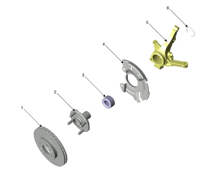
1. Brake disc
2. Front hub
3. Hub bearing
4. Dust cover
5. Front axle
6. Snap ring
1.Loosen the wheel nuts slightly.Raise the vehicle, and make sure it is securely supported.
2.Remove the front wheel and tire (A) from the front hub.
Tightening torque :107.9 - 127.5 N.m (11.0 - 13.0 kgf.m, 79.6 - 94.0 lb-ft)
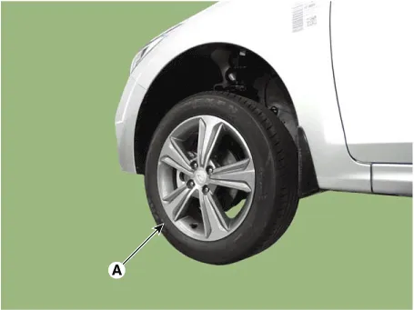

• Be careful not to damage the hub bolts when removing the front wheel and tire.
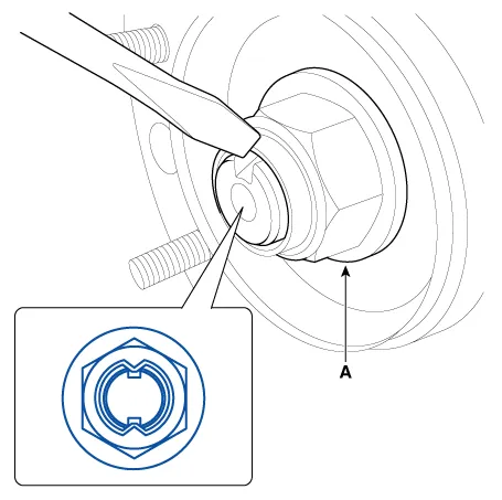
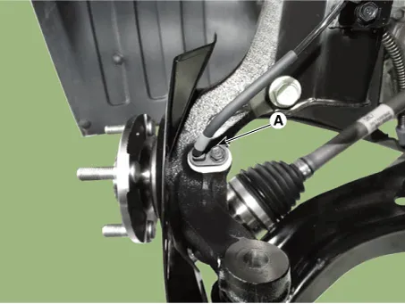
3.Loosen the driveshaft caulking nut (A).
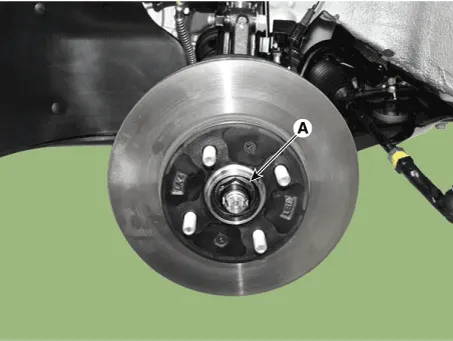

• The driveshaft lock nut (A) should be replaced with new ones.
• After installation driveshaft lock nut, stake the lock nut using a chisel and hammer as shown in the illustration below.
Caulking depth : 1.5 mm (0.591 in.)
4.Remove the front brake caliper.
5.Remove the tie rod end ball joint.
(1)Remove the split pin (C).
(2)Loosen the nut (B).
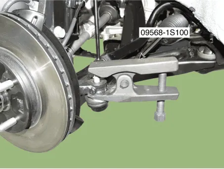
(3)Using SST(09568-1S100), separate the ball joint (A) from the knuckle.
Tightening torque :24.5 - 34.3 N.m (2.5 - 3.5 kgf.m, 18.1 - 25.3 lb-ft)
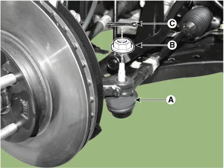

• Do not reuse the split pin (C).
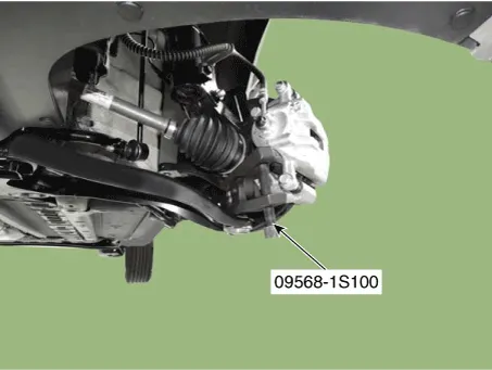
6.Loosen the lower arm nut (A) and then remove the lower arm ball joint by using SST(09568-1S100).
Tightening torque : 58.8 - 70.6 N.m (6.0 - 7.2 kgf.m, 43.4 - 52.1 lb-ft)
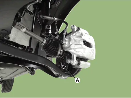

• Do not reuse the lower arm lock nut (A).
• Be careful not to damage the ball joint boots.
7.Loosen the bolt and then remove the wheel speed sensor (A).
Tightening torque : 7.8 - 11.8 N.m (0.8 - 1.2 kgf.m, 5.8 - 8.7 lb-ft)
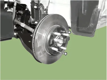
8.Loosen the screw and the remove the front disc.
Tightening torque :4.9 - 5.9 N.m (0.5 - 0.6 kgf.m, 3.6 - 4.3 lb-ft)
9.Using a plastic hammer, remove the front driveshaft (A) from the hub bearing assembly (B).


• Be careful not to damage the driveshaft, front sub frame or stabilizer link.
10.Loosen the strut mounting bolts nuts and then remove the knuckle assembly.
Tightening torque :98.1 - 117.7 N.m (10.0 - 12.0 kgf.m, 72.3 - 86.8 lb-ft)
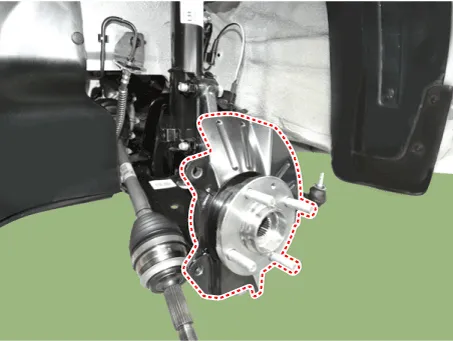

• Be careful not to damage the ball joint boots.
11.Install in the reverse order of removal.
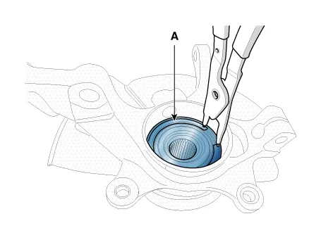
1.Using the snap ring pliers, remove the snap ring (A).
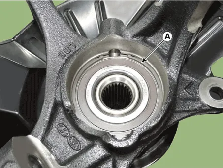
2.Remove the hub assembly from the knuckle assembly.
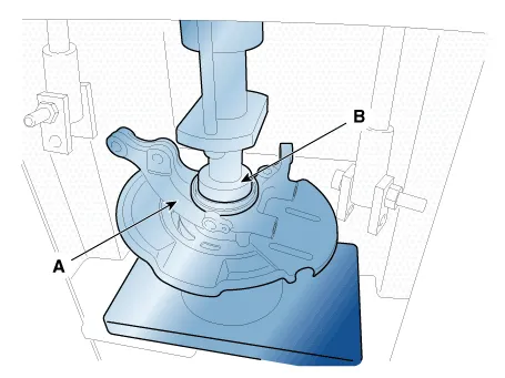
(1)Install the front knuckle assembly (A) on press.
(2)Lay a suitable adapter (B) upon the hub assembly shaft.
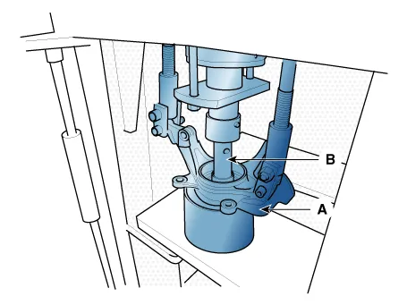
3.Remove the dust cover (A).

4.Remove the hub bearing inner race from the hub assembly.
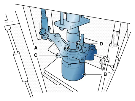
(1)Install a suitable tool (A) for removing the hub bearing inner race on the hub assembly.
(2)Lay the hub assembly and tool (A) upon a suitable adapter (B).
(3)Lay a suitable adapter (C) upon the hub assembly shaft.
(4)Remove the hub bearing inner race (D) from the hub assembly by using press.
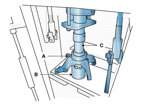
5.Remove the hub bearing outer race from the knuckle assembly.
(1)Lay the hub assembly (A) upon a suitable adapter (B).
(2)Lay a suitable adapter (C) upon the hub bearing outer race.
(3)Remove the hub bearing outer race from the knuckle assembly by using press.
6.Replace hub bearing with a new one.
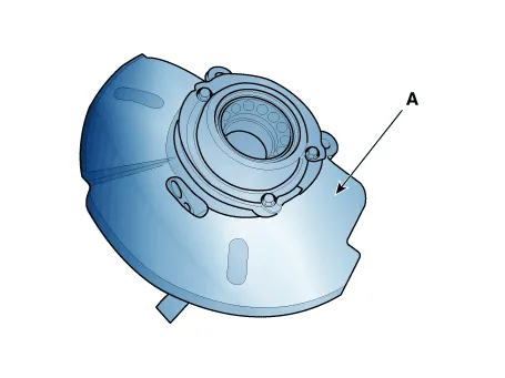
1.Install the dust cover (A).
2.Install the hub bearing to the knuckle assembly.
(1)Lay the knuckle assembly (A) on press.
(2)Lay a new hub bearing upon the knuckle assembly (A).
(3)Lay a suitable adapter (B) upon the hub bearing.
(4)Install the hub bearing to the knuckle assembly by using press.
• Do not press against the inner race of the hub bearing because that can cause damage to the bearing assembly. Always use a new wheel bearing assembly.
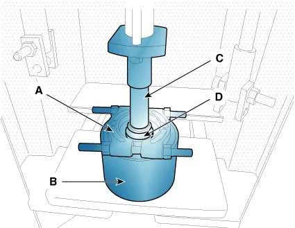
3.Install the hub assembly to the knuckle assembly.
(1)Lay the hub assembly (A) upon a suitable adapter (B).
(2)Lay the knuckle assembly (C) upon the hub assembly (A).
(3)Lay a suitable adapter (D) upon the hub bearing.
(4)Install the hub assembly (A) to the knuckle assembly (C) by using press.

• Do not press against the inner race of the hub bearing because that can cause damage to the bearing assembly.
4.Install the snap ring (A).


Other information:
Hyundai Accent (HC) (2017 - 2022) Service Manual: Storage compartment
Use the storage compartments in your Hyundai Accent to keep everyday items organized and secure, and always stow loose objects before driving. WARNING Never store cigarette lighters, propane cylinders, or other flammable/explosive materials in the vehicle. These items may catch fire and/or explode if the vehicle is exposed to hot temperatures for extended periods.Front seat 1. Forward and backward — adjust distance to pedals and steering wheel for safe control 2. Seatback angle — set a comfortable upright angle that supports your back 3. Seat height (Driver's seat) — adjust eye level for clear visibility over the hood 4. Headrest — align with the head for whiplash protection in a collision 5. Seat warmer — comfort feature for cold weather driving (if equipped) Rear seat 6.
Contents
Categories
- Manuals Home
- Hyundai Accent Owners Manual
- Hyundai Accent Service Manual
- Questions & Answers
- Video Guides
- Useful Resources
- New on site
- Most important about car
- Privacy Policy

0.0072