Hyundai Accent (HC): Brake System (ABS/ESC) / Forward Collision-Avoidance Assist (FCA) System
Contents:
Description and Operation
– FCA system is designed to help avoid a potential collision or reduce its impact when drivers applies inadequate, delayed or no brakes at all to avoid a collision.
– The system detects the risk factors on the road by using the frontal impact sensor and warn the driver and activate the emergency brake to prevent collision or reduce collision speed.
The following is the system control process1.Confirm the object to be protected by FCA system (vehicles and pedestrians) by using the analyzed data.
2.Calculate the speed reduction depending on the speed, distance, existence or nonexistence of preceding vehicle.
3.Report the "required speed reduction" to Electronic Stability Control (ESC) (CAN Comm.)
4.ESC performs automatic control after calculating the required torque to achieve "required speed reduction" (CAN Comm.).
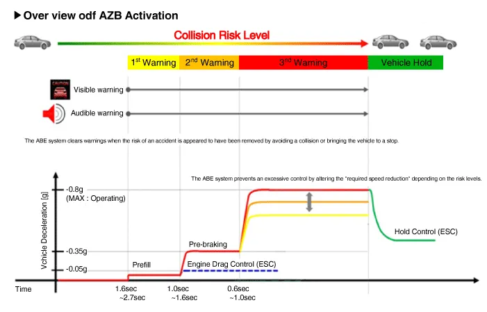
• Step 1 : Issue a visual (display) and vocal alarm when a danger is detected.
• Step 2 : Reduce engine torque and activates FCA when there is a high chance of collision.
• Step 3 : Activate emergency brake when a collision is imminent.
• After stopping the vehicle : Maintain the braking control for a certain time and then release it.

• Braking power is adjusted depending on the risk levels of collision, but it is released immediately when it detects the driver's action to avoid a collision.
1)When it exceeded the maximum operation speed.
2)When it detected driver's action to avoid a collision such as sudden steering changes.
3)When the shift lever is in R or P
4)When you pressed the accelerator pedal half way.

1)When you drive at 80km/h or faster, the system does not go to step 3 of emergency braking.- Full auto braking is not available.
2)While driving at 80km/h or slower on a straight or slightly curved road, the system performs three steps after issuing a warning.- But a collision may occur at 30km/h or faster depending on the road conditions.
3)While driving at 80km/h or slower on a straight or slightly curved road, after a visual and vocal warning, FCA is activated to reduce the vehicle speed.
4)At 80km/h or faster, it's impossible to avoid a collision. Offset should be less than 50%.
5)FCA does not work on the vehicles backing up or resisting.

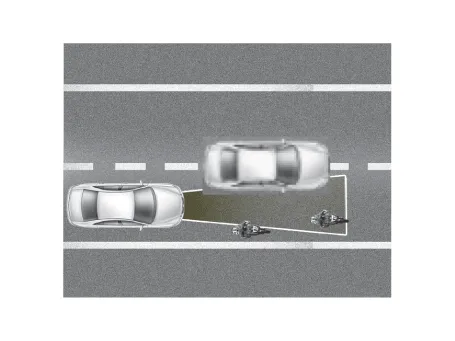
• Offset : Rate of non-overlapping on the line between the front driving car and my car
1)Offset 100% :

2)Offset 0% :
Components and Components Location
– Detection device (radar) that can recognize potential obstacles in the front.
– Human-Machine Interface (HMI) to warn driver or change settings.
– Braking system to automatically brake the car
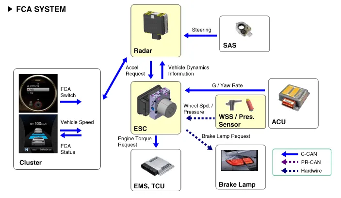
FCA Radar


| No | Terminal function |
| 1 | - |
| 2 | C-CAN LOW |
| 3 | C-CAN HIGH |
| 4 | GND |
| 5 | IGN1 |
| 6 | - |
| 7 | - |
| 8 | - |
– The ON/OFF for FCA is included in the USM (User Setting Menu) and the default is ON.
– While IGN is ON, it stays at ON, however, the driver's settings do not last next time when IGN is newly ON.
– When ESC is OFF, FCA is also turned OFF.
1.Turn the ignition switch off and disconnect the battery (-) terminal.
2.Remove the front bumper cover.(Refer to Body - "Front Bumper Assembly")
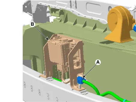
3.Disconnect the FCA radar connector (A).
4.Remove the FCA radar (B) after loosening the mounting nuts.
Tightening torque :6.7 - 7.4 N.m (0.68 - 0.75 kgf.m, 4.9 - 5.4 lb-ft)
1.Installation is the reverse of removal.

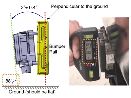
• The vertical installation angle of the unit must be within 2˚± 0.4˚. (not 0 degree)※ Before installing the bumper onto the vehicle, measure the vertical angle of the unit with a protractor as shown.
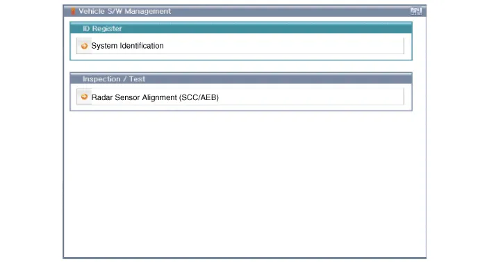
2.Perform FCA variant coding
3.Perform the FCA radar alignment.

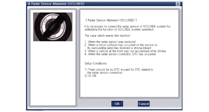
• The FCA unit has been reinstalled or replaced with a new one.
• The radar sensor or the surrounding parts have been impacted by collision.
• The sensor cannot detect a vehicle in front.
• The Steering Angle Sensor (SAS) has been replaced or adjusted.

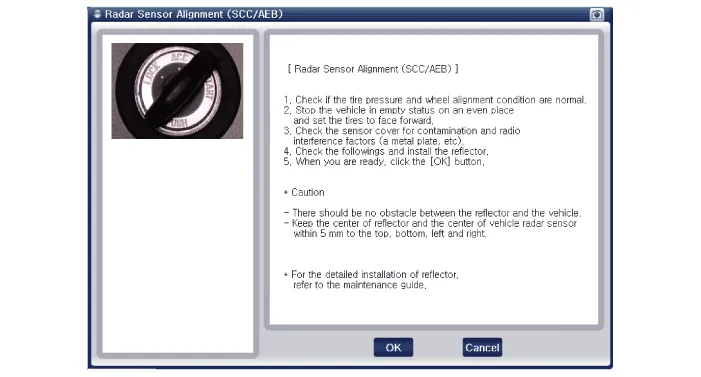
• Park the vehicle on a level ground.
• Take out heavy luggage from the vehicles’ seats or trunk.
• Set all tires according to the specified pressure.
• Check wheel alignment.
• Check that the front surface of the AEB unit is clean.
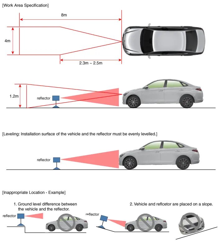
1.Park the vehicle on a level ground.

• Adjustment may not be accurate if the vehicle and reflector are placed on different ground levels or on a slope.
• Perform in an area with minimum clearance of 8 m to the front, 4 m wide, and 1.2 m above the ground.
• Remove heavy objects from inside of the vehicle (seating area and trunk).
• Ensure that all tires are filled with specified air pressure.
• Remove objects (metal plates, resins, etc.) that may cause electric signal interference from the area where sensor alignment is performed.
• Be sure that the vehicle is not moved and free from vibration when performing sensor alignment (getting in/out or opening/closing doors).
• Check that radiator grille and sensor cover are not dirty.
• Check for correct wheel alignment.
• Do not turn OFF the power when performing sensor alignment.
• Power supplied to the radar sensor must be between 9V - 16V.
• Temperature in the area where sensor alignment is performed must be between -30 - 60°C.
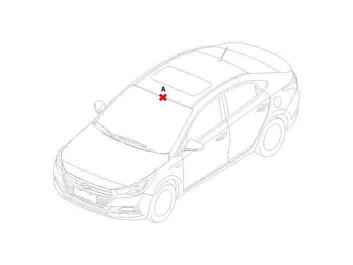
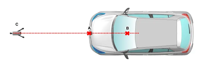
2.Mark the center point on top of wind glass (A).
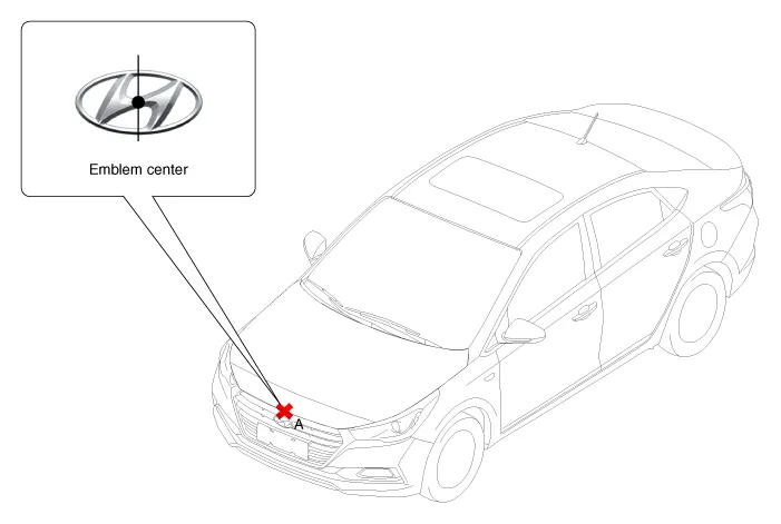
3.Mark the center point of emblem (A).
4.Mount the FCA Calibration Laser [SST No. : 09964-C1200] onto the tripod [SST No. : 09964-C1300].
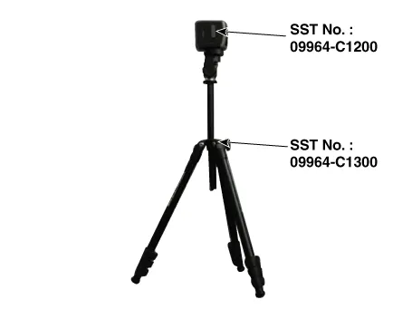
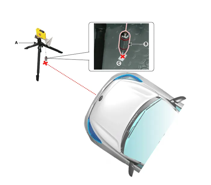
5.Install the vertical/horizontal laser [SST No. : 09964-C1200] (A) at least 2.5 m to the front of the vehicle.
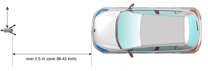
6.Match the vertical line of laser to (A) and (B) using the vertical/horizontal laser (C) [SST No. : 09964-C1200].
7.Mark (C) at 2.3 - 2.5m (90.55 - 98.42 inch) from (A) in front of the vehicle.


• If possible, perform calibration at the 2.5m position.
8.Remove the FCA Calibration Laser [SST No. : 09964-C1200] (B) from the tripod [SST No. : 09964-C1300] (A).
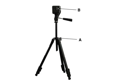
9.Mount the reflector [SST No. : 09964-C1100] (B) onto the tripod [SST No. : 09964-C1300] (A).
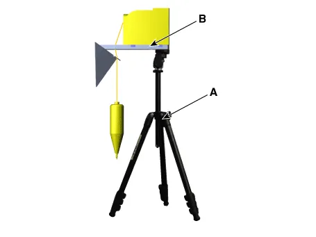
10.Align the vertical weight (B) of the FCA Calibration Reflector [SST No. : 09964-C1100] (A) with the point (C).
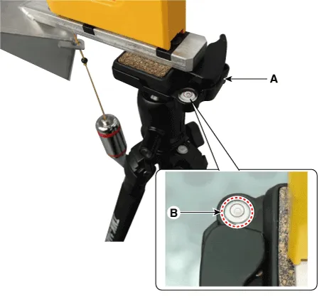
11.Using the bubble level (B) of the tripod [SST No. : 09964-C1300] (A), set the reflector horizontally.
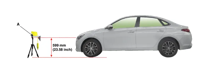
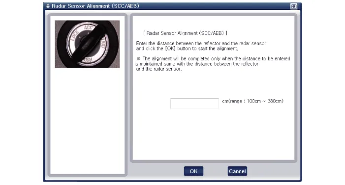
12.Set the height of the FCA calibration reflector [SST No. : 09964-C1100] (A) to 599 mm (23.58 inch).
13.Visually check again the radar sensor and the surface of the front bumper for the following.

• Make sure that there is no debris, or reflecting object on the surface of the radar.
• Make sure that there is no debris, or reflecting object on the radiator grille.
14.Connect the GDS to the DLC of the vehicle and start sensor alignment.

• If the engine is running, the vibration may cause inaccurate sensor alignment, so perform sensor alignment in IG ON mode.
15. After correctly selecting the vehicle model, select "FCA Alignment" from the auxiliary functions in GDS Menu.
16.Perform sensor alignment as indicated on the GDS monitor.
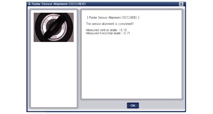
17. In case of sensor alignment failure, check the alignment conditions. Turn the ignition key OFF, then reperform the sensor alignment procedure.


Other information:

Contents
Categories
- Manuals Home
- Hyundai Accent Owners Manual
- Hyundai Accent Service Manual
- Questions & Answers
- Video Guides
- Useful Resources
- New on site
- Most important about car
- Privacy Policy

0.0062