Hyundai Accent (HC): Charging System / Alternator
| Item | Specification | |
| Rated voltage | 13.5V, 130A | |
| Speed in use | 1,000 - 18,000 rpm | |
| Voltage regulator | IC Regulator built-in type | |
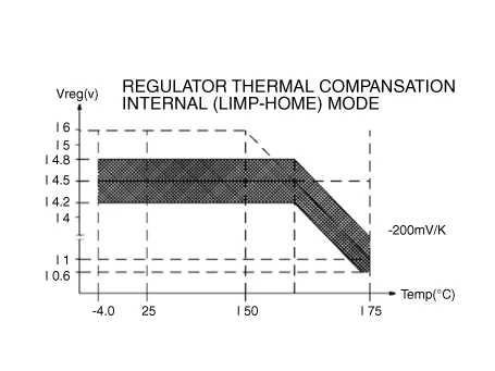
| Regulator Setting Voltage | External mode | 10.6 - 16 ± 0.3V |
| Internal mode | 14.5 ± 0.3V | |
| Temperature Gradient | External mode | 0 ± 2 mV / °C |
| Internal mode | -3.5 ± 2 mV / °C | |
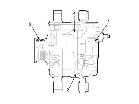
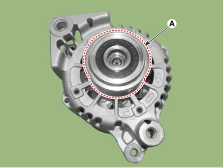
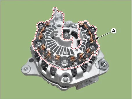
1. Brush
2. Pulley
3. Rotor
4. Stator
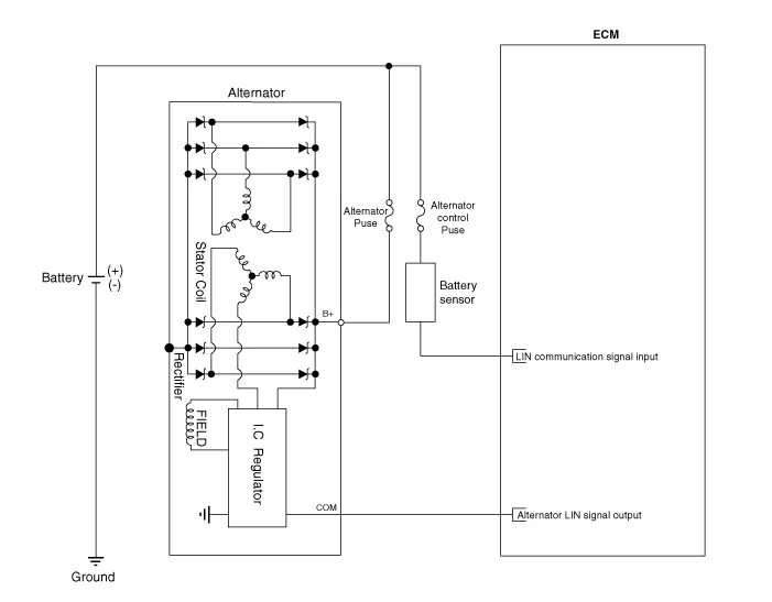

• COM signal - When controlling the voltage generated, the ECM sends the target voltage data to the alternator via a LIN signal.
• B+ terminal - The output voltage from the generator travels to the battery via the B+ terminal.
1.Turn ignition switch OFF and disconnect the battery negative (-) terminal.
2.Remove the drive belt.(Refer to Engine Mechanical System - "Drive Belt")
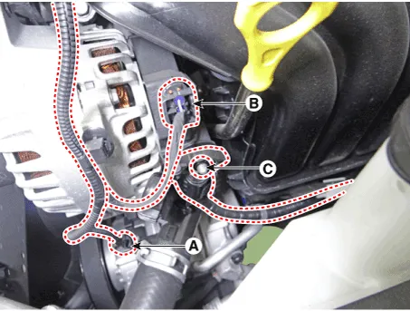
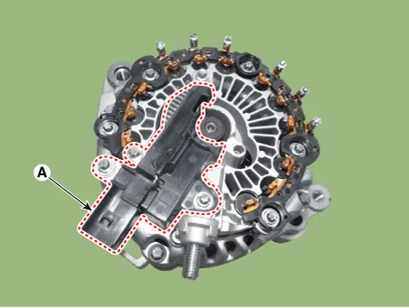
3.Disconnect the air compressor connector (A) and the alternator connector (B), and remove the cable (C) from alternator "B" terminal.
Alternator B-terminal cable mounting nut :18.6 - 24.5 N.m (1.9 - 2.5 kgf.m, 4.1 - 5.5 Ib-ft)
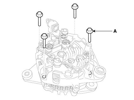
4.Loosen the mounting bolts (A).
Alternator lower bolt :29.4 - 41.2 N.m (3.0 - 4.2 kgf.m, 21.7 - 30.4 Ib-ft)
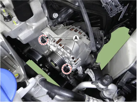
5.Remove the alternator (A).
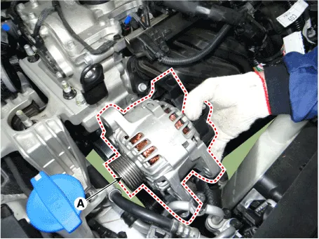
6.Install in the reverse order of removal.
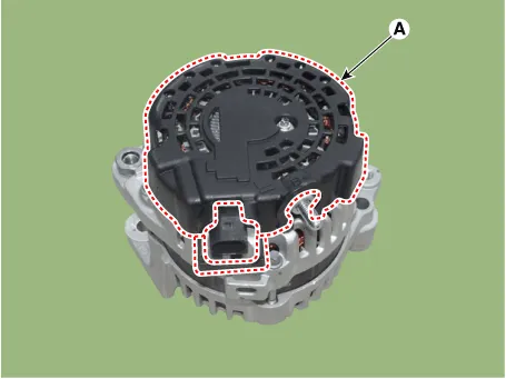
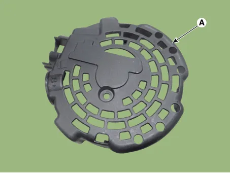
1.Remove the rear cover (A).
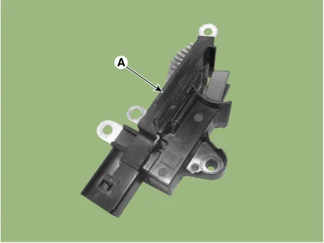
2.Remove the mounting bolts (A) and the regulator assembly.

• When installing, replace with new OAP cap.
3.Remove the OAP cap.
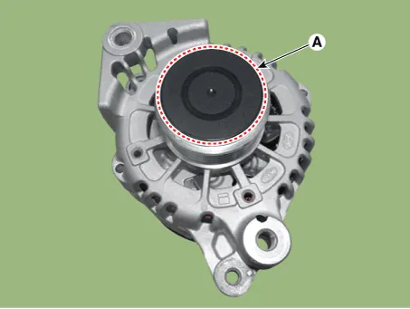

• When installing, replace with new OAP cap.
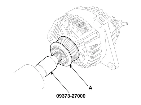
4.Remove the OAP pulley (A) using the special tool (09373-27000).
5.Remove the rectifier assembly (A) after disconnecting the stator leads.
6.Remove the 4 through bolts (A).
7.Disconnect the rotor (A) and bracket (B).
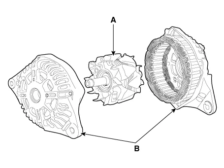
8.Install in the reverse order of removal.
1.Reassemble in the reverse order of disassembly.

• When reassembling OAP pulley, replace with new OAP cap.
1.Check that there is continuity between the slip rings (C).
2.Check that there is no continuity between the slip rings and the rotor (B) or rotor shaft (A).
3.If the rotor fails either continuity check, replace the alternator.
1.Check that there is continuity between each pair of leads (A).
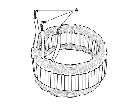
2.Check that there is no continuity between each lead and the coil core.
3.If the coil fails either continuity check, replace the alternator.


Other information:
Hyundai Accent (HC) (2017 - 2022) Service Manual: Position Switch
- Specifications ItemSpecification Power supply (V)4.5 - 5.5V Output typePWM (S1, S2), ON/OFF (Ps, Ns) - Component Location 1. Position switch2. Manual control lever - Circuit Diagram - Inspection • Inspect the connector thoroughly for looseness, poor connection, bending, corrosion, contamination, deformation, or damage.Hyundai Accent (HC) (2017 - 2022) Service Manual: Description and Operation
- Description This specification applies to HCU (Hydraulic Control Unit) and ECU (Electronic Control Unit) of the HECU. (Hydraulic and Electronic Control Unit)This specification is for the wiring design and installation of ABS ECU.This unit has the functions as follows. – Input of signal from the wheel speed sensors attached to each wheel.
Categories
- Manuals Home
- Hyundai Accent Owners Manual
- Hyundai Accent Service Manual
- Questions & Answers
- Video Guides
- Useful Resources
- New on site
- Most important about car
- Privacy Policy

0.0055