Hyundai Accent (HC): Engine Electrical System / Charging System
Contents:
Description and Operation
Repair procedures ➤
Troubleshooting

• Be careful not to short-circuit the wiring by the body or other wirings.
• In case of discharging problem, measure dark current at all times.(Refer to Charging System - "Dark Current Inspection")
• When checking the alternator main fuse, perform continuity test and voltage test between terminals as well as visual check to confirm normal operation.
• When checking the ground, repair or replace after inspecting for defective ground cable, defective installation or defective contact due to foreign object.
• It is not recommended to use non-authentic parts as installing non-authentic parts may cause malfunction of charging system.
• Be careful as misassembly may cause short-circuit of wiring, which may result in battery discharge.
• As it will reset and appear as normal if the battery negative (-) terminal is disconnected while measuring dark current, measure by using a hook meter without disconnecting the negative (-) terminal.
• Note that there may be various phenomenons / possible causes / repair measures apart from above.
• For more effective repairs, refer to DTC guide and ETM.
| Symptom | Suspected Area | Remedy |
| Charging warning lamp does not turn on during IG ON. | Broken alternator main fuse | Inspect / Repair / Replace fuse. |
| Broken instrument cluster fuse | Inspect / Repair / Replace fuse. | |
| Broken instrument cluster internal bulb | Inspect / Repair / Replace instrument cluster. | |
| Defective connection of wiring connector | Inspect / Repair / Replace wiring connection. | |
| Defective voltage regulator or alternator | Inspect / Repair / Replace voltage regulator or alternator. | |
| Defective connection of battery terminal | Inspect tightening of (+) and (-) battery terminals to specified torque. | |
| Communication error | Inspect wiring between regulator and ECM. | |
| Inspect transmission signal of ECM. | ||
| Inspect / Repair / Replace alternator if the wiring and ECM are normal. | ||
| Charging warning lamp does not turn off during engine running. | Worn drive belt or lack of tension | Inspect / Repair / Replace drive belt. |
| Defective connection, corroded or worn battery cable | Inspect connection of battery cable and Inspect / Repair / Replace cable. | |
| Broken alternator main fuse | Inspect / Replace alternator main fuse or battery cable. | |
| Defective voltage regulator or alternator | Inspect / Replace voltage regulator or alternator. | |
| Defective wiring | Inspect / Replace wiring. | |
| Defective instrument cluster | Inspect / Replace instrument cluster | |
| Slip in alternator pulley | Inspect / Replace alternator pulley. | |
| Adjust tension / Replace drive belt. | ||
| Defective connection of battery terminal | Inspect tightening of (+) and (-) battery terminals to specified torque. | |
| Charging warning lamp turns on. | Slip, worn or lack of tension in drive belt | Adjust tension / Replace drive belt. |
| Inspect / Replace auto tensioner (only for auto tensioner type). | ||
| Error in Alternator Management System (AMS) voltage | Inspect battery sensor connecting harness and connection with body. | |
| Error in battery sensor | Inspect / Repair / Replace battery sensor. | |
| Short between battery sensor wiring and body | Inspect / Repair / Replace battery sensor. | |
| Defective alternator L terminal output power | Inspect / Repair / Replace alternator or regulator. | |
| Degradation due to defective contact of battery (+) terminal | Check tightening to specified torque / Inspect / Repair / Replace battery wiring. | |
| Short in alternator connecting extension connector internal pin | Inspect / Repair / Replace wiring. | |
| Short circuit between body and mission ground | Inspect / Repair / Replace ground. | |
| Communication error | Inspect / Repair / Replace wiring between regulator and ECM. | |
| Inspect transmission signal of ECM. | ||
| Inspect / Repair / Replace alternator if wiring and ECM are normal. | ||
| Short in the middle of connection to alternator L terminal (L terminal applied vehicle model) | Inspect / Repair / Replace wiring. | |
| Drive belt rotation stops due to slip in crankshaft damper pulley or defective pulley. | Inspect or replace crankshaft damper pulley / Inspect, repair or replace drive belt tensioner bearing. | |
| Slip, worn or lack of tension in drive belt | Adjust tension / Inspect / Repair / Replace drive belt. | |
| Defective voltage regulator | Inspect / Repair / Replace voltage regulator. | |
| Defective alternator | Inspect / Repair / Replace alternator. | |
| Broken alternator main fuse | Inspect / Repair / Replace alternator main fuse or battery wiring cable. | |
| Defective ground | Inspect / Repair / Replace ground. | |
| Discharged battery | Adjust tension / Inspect / Repair / Replace drive belt. | |
| Inspect / Repair / Replace wiring connection. | ||
| Inspect / Repair / Replace alternator main fuse. | ||
| Inspect / Repair / Replace alternator. | ||
| Inspect / Repair / Replace voltage regulator. | ||
| Inspect / Repair / Replace battery unit. | ||
| Inspect for dark current / Repair / Replace. | ||
| Learn / Inspect / Repair / Replace battery sensor. | ||
| Inspect for short / Repair / Replace battery cable. | ||
| Inspect / Repair / Replace ECM. | ||
| Inspect / Repair / Replace body electrical related parts. | ||
| Inspect / Repair / Replace installation status of alternator connector. | ||
| Inspect / Repair / Replace tightening of (+) and (-) battery terminals to specified torque. | ||
| Swollen battery | Defective battery | Inspect / Replace battery. |
| Defective voltage regulator or alternator | Inspect / Repair / Replace voltage regulator or alternator. | |
| Defective charging related parts or wiring | Inspect / Repair / Replace charging related parts and wiring. | |
| After inspection, repair or replace related parts in case of malfunction. | ||
Alternator
| Item | Specification | |
| Rated voltage | 13.5V, 130A | |
| Speed in use | 1,000 - 18,000 rpm | |
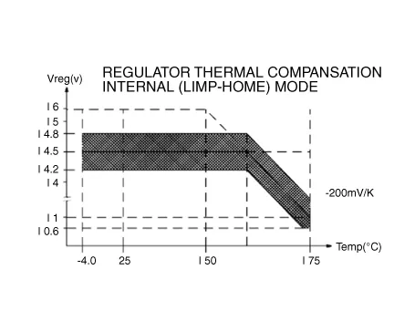
| Voltage regulator | IC Regulator built-in type | |
| Regulator Setting Voltage | External mode | 10.6 - 16 ± 0.3V |
| Internal mode | 14.5 ± 0.3V | |
| Temperature Gradient | External mode | 0 ± 2 mV / °C  |
| Internal mode | -3.5 ± 2 mV / °C | |
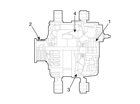
1. Brush
2. Pulley
3. Rotor
4. Stator
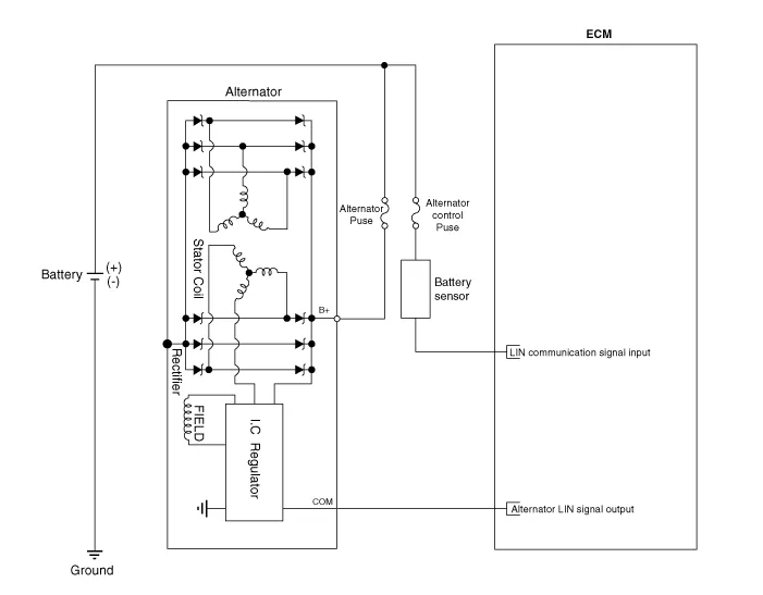

• COM signal - When controlling the voltage generated, the ECM sends the target voltage data to the alternator via a LIN signal.
• B+ terminal - The output voltage from the generator travels to the battery via the B+ terminal.
1.Turn ignition switch OFF and disconnect the battery negative (-) terminal.
2.Remove the drive belt.(Refer to Engine Mechanical System - "Drive Belt")
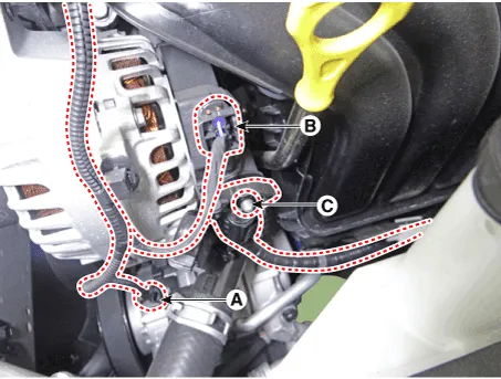
3.Disconnect the air compressor connector (A) and the alternator connector (B), and remove the cable (C) from alternator "B" terminal.
Alternator B-terminal cable mounting nut :18.6 - 24.5 N.m (1.9 - 2.5 kgf.m, 4.1 - 5.5 Ib-ft)
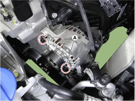
4.Loosen the mounting bolts (A).
Alternator lower bolt :29.4 - 41.2 N.m (3.0 - 4.2 kgf.m, 21.7 - 30.4 Ib-ft)
5.Remove the alternator (A).
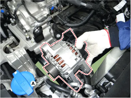
6.Install in the reverse order of removal.
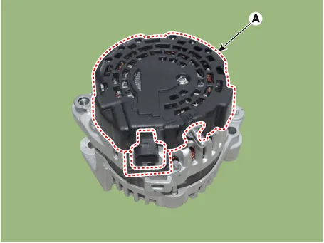
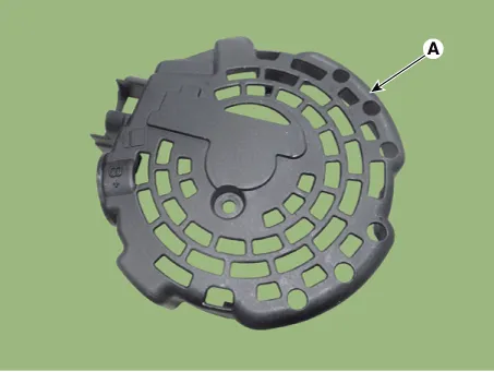
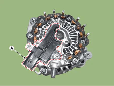
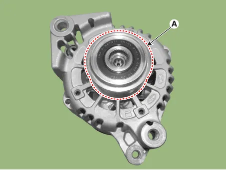
1.Remove the rear cover (A).
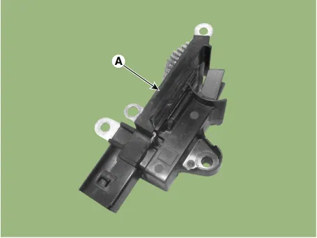
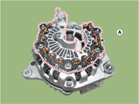
2.Remove the mounting bolts (A) and the regulator assembly.

• When installing, replace with new OAP cap.
3.Remove the OAP cap.
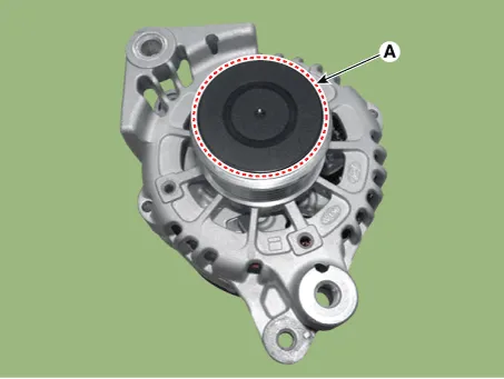

• When installing, replace with new OAP cap.
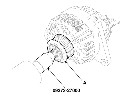
4.Remove the OAP pulley (A) using the special tool (09373-27000).
5.Remove the rectifier assembly (A) after disconnecting the stator leads.
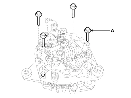
6.Remove the 4 through bolts (A).
7.Disconnect the rotor (A) and bracket (B).
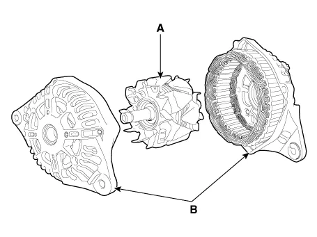
8.Install in the reverse order of removal.
1.Reassemble in the reverse order of disassembly.

• When reassembling OAP pulley, replace with new OAP cap.
1.Check that there is continuity between the slip rings (C).
2.Check that there is no continuity between the slip rings and the rotor (B) or rotor shaft (A).
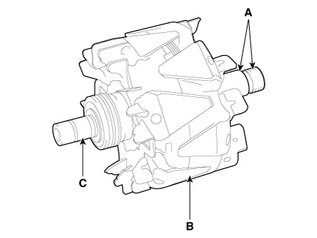
3.If the rotor fails either continuity check, replace the alternator.
1.Check that there is continuity between each pair of leads (A).
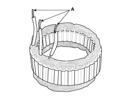
2.Check that there is no continuity between each lead and the coil core.
3.If the coil fails either continuity check, replace the alternator.
Battery ➤
Battery Sensor

• When battery sensor signal fault occurs, check whether the parasitic draw is not abnormal (Refer to vehicle parasitic current inspection)

1)Turn the ignition switch ON/OFF.
2)Leave the vehicle in parking mode for more than 4 hours.
3)After 4 hours, check that the SOC (State of charge) of battery is displayed on GDS properly.

• When replacing the battery, it should be the same (type, capacity and brand) as originally installed on your vehicle. If a battery of a different type is installed, the battery sensor may recognize the battery to be abnormal.
• When installing the ground cable on the negative post of battery, tighten the clamp with specified torque of 3.9 - 5.9 N.m (0.4 - 0.6 kgf.m, 3.0 - 4.4 lb-ft). An excessive tightening torque can damage the PCB internal circuit and the battery terminal.
• When recharging the battery, ground the negative terminal of the booster battery to the vehicle body.
1.Turn the ignition switch OFF.
2.Disconnect the battery negative (-) terminal (A).
Battery negative (-) terminal tightening nut :8.0 - 10.0 N.m (0.8 - 10.0 kgf.m, 5.9 - 7.4 lb-ft)
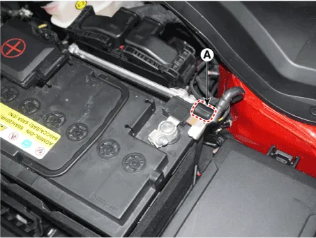
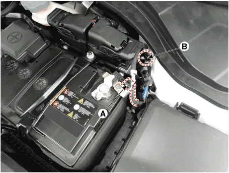
3.Disconnect the battery sensor connector (A).
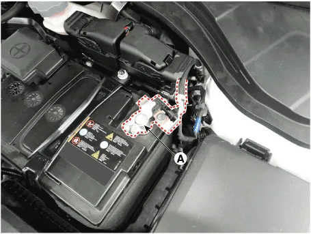
4.Remove the battery sensor by loosening the mounting bolts (B).
Battery sensor cable mounting bolt (Chassis ground) :27.0 - 33.0 N.m (2.8 - 3.4 kgf.m, 19.9 - 24.3 lb-ft)
5.Install in the reverse order of removal.

• For the vehicle equipped with a battery sensor, be careful not to damage the battery sensor when the battery is replaced or recharged.
1)When replacing the battery, it should be same one (type, capacity and brand) that is originally installed on your vehicle. If a battery of a different type is replaced, the battery sensor may recognize the battery to be abnormal.
2)When installing the ground cable on the negative post of battery, tighten the clamp with specified torque. An excessive tightening torque can damage the PCB internal circuit and the battery terminal.
3)When recharging the battery, ground the negative terminal of the booster battery to the vehicle body.
1.Turn the Iginition switch ON and OFF.
2.Park the vehicle for about 4 hours with the hood and all doors closed.


Other information:
Hyundai Accent (HC) (2017 - 2022) Service Manual: Rear Disc Brake
- Components 1. Return spring2. Operating lever3. Stopper4. Guide rod pin5. Guide rod boot6. Caliper carrier7. Pad retainer8. Brake pad9. Pad return spring10.Caliper body - Removal 1.Loosen the wheel nuts slightly.Raise the vehicle, and make sure it is securely supported. 2.Remove the rear wheel and tire (A) from front hub.Tightening torque :107.Hyundai Accent (HC) (2017 - 2022) Service Manual: Explanation of scheduled maintenance items
Engine Oil and Filter The engine oil and filter should be changed at the intervals specified in the maintenance schedule. If the Hyundai Accent is being driven in severe conditions, more frequent oil and filter changes are required to protect the engine from accelerated wear and sludge buildup. Drive Belts Inspect all drive belts for evidence of cuts, cracks, excessive wear or oil saturation and replace if necessary.
Contents
Categories
- Manuals Home
- Hyundai Accent Owners Manual
- Hyundai Accent Service Manual
- Questions & Answers
- Video Guides
- Useful Resources
- New on site
- Most important about car
- Privacy Policy

0.0062