Hyundai Accent (HC): Steering System / Motor Driven Power Steering
Contents:
- Description and Operation
- Schematic Diagrams
- Components and Components Location
- Repair procedures
- MDPS Motor
- MDPS Control Unit
- MDPS Column and Housing
- MDPS Assembly
- Steering Gear Box
Description and Operation
Note With Regard to diagnosis
| Trouble factor | Check item | Trouble symtom | Explanation | Note | ||||||||||
| Drop, impact, and overload | Motor | Abnormal noise |
|
| ||||||||||
| ECU | Circuit damage
| |||||||||||||
| Torque sensor | Insufficient steering effort | Overload to INPUT shaft can cause malfunction of the torque sensor |
| |||||||||||
| Shaft | Insufficient steering effort (Uneven between LH and RH) | Do not use the impacted MDPS | ||||||||||||
| Pull/Dent | Harness |
| Disconnection between harness connecting portion and harness | Do not overload the harness | ||||||||||
| Abnormal storage temperature | Motor/ECU | Abnormal steering effort by improper operation of the motor/ECU |
|
|
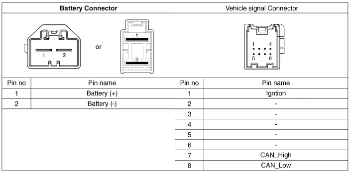
Schematic Diagrams
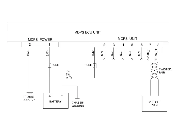
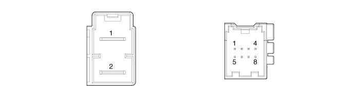
| Type | Pin No | Description |
| Battery | 1 | Battery + |
| 2 | Battery - | |
| VSS | 1 | IGN |
| 2 | - | |
| 3 | - | |
| 4 | - | |
| 5 | - | |
| 6 | - | |
| 7 | HIGH CAN | |
| 8 | LOW CAN |
Components and Components Location
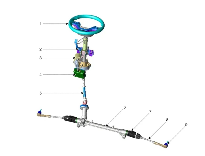
1. Steering wheel
2. Steering column
3. MDPS motor
4. MDPS ECU
5. Universal joint
6. Steering gear box
7. Bellows
8. Tie rod
9. Tie rod end
Repair procedures
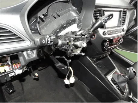
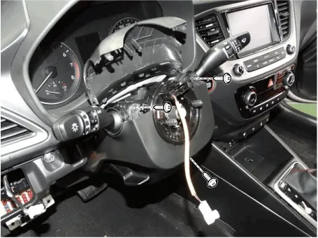
1.Checking Connectors and Wiring.Check for damage, push-back, or improper connection in each connector and wiring.
(1)Check the wiring on the vehicle side.
– Check for open / short - circuit due to faulty connection, damage, or foreign substance.
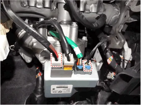
(2)Check the wiring on the ECU side (motor 3 - phase power).
– Check for open / short - circuit due to faulty connection, damage, or foreign substance.

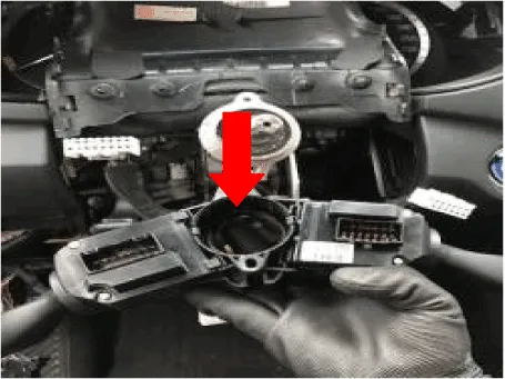
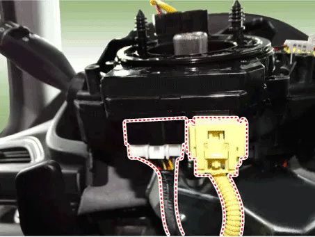
(3)Check the motor connector.
– Terminal Expansion and damage
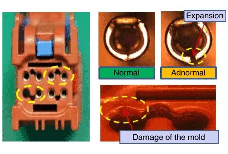

• Must be replaced the MDPS motor if occur terminal expansion and damage.
(4)Check the motor wiring.
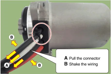

• Must be replaced the MDPS motor if occur damage or problem.
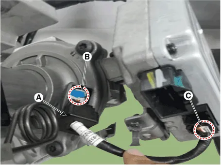
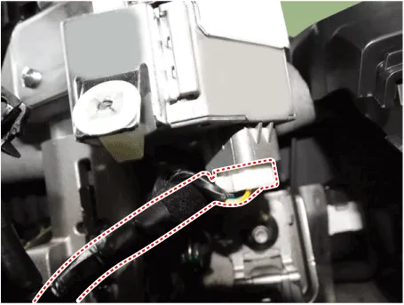
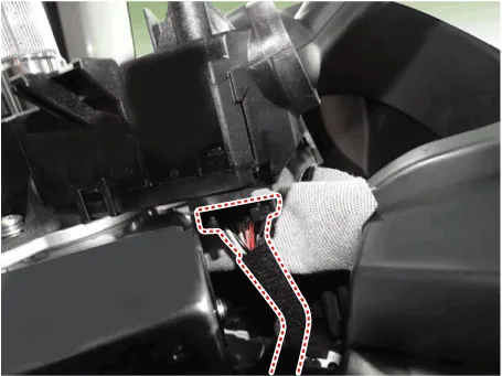
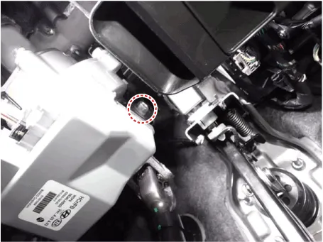
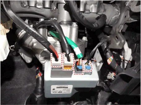
(5)Remove the grommet (A) and then check the wiring on the TAS side (B) and ECU side (C).
– Check for damage, push-back, or improper connection in each connector and wiring.

| DTC | Problem | First analysis method | How to repair |
| C1290 | Torque sensor signal error | First erase DTC, check connector connection. | In case of reoccurrence, replace column & housing. |
| C1112 | Torque sensor voltage error | Check connector between torque sensor and ECU. | In case of reoccurrence, replace ECU. |
| C1705 | ECU hardware error | First erase DTC and then check, check ECU connector. | |
| C1604 | ECU over/discharge error | ||
| C2413 | ECU hardware error | ||
| C2400 | Motor signal error | IIn case of reoccurrence, replace motor. | |
| C2401 | Motor circuit error | ||
| C2412 | Motor voltage supply error | First erase DTC and check, Check ECU/motor connector. | First replace ECU. In case of reoccurrence, replace motor. |
| C1259 | Angle sensor signal error | After Resetting zero point & erasing DTC, check connector connection condition. | In case of reoccurrence, replace column & Housing. |
| C1261 | Zero-setting error | After Resetting zero point, recheck. | Reset the zero-setting. |
| C1102 | Battery voltage problem | Check battery voltage condition. | Recharge battery voltage. |
| C1696,C1697 | SPAS signal error | Check SPAS. | Erase DTC (MDPS is not to be replaced). |
| C1612,C1646 | TCU signal error | Check TCU. | |
| C1628,C1656 | Instrument cluster signal error | Check instrument cluster. | |
| C1692,C1693 | VSM signal error | Check VSM. | |
| C1260 | Angle sensor signal error | After resetting the angle, recheck. If C1259 does not occur, check CAN line. | Reset Angle sensor. Erase DTC. |
| C1611 | CAN time out EMS | 1. Check G-SCAN condition. 2. Check connector connection. 3. Check ECU CAN line. 4. Check MDPS ground line. | Check the EMS CAN Line. |
| C1616 | CAN BUS OFF | Check the chassis CAN Line. | |
| C1622 | Vehicle speed signal error | Check the EMS (Engine ECU). | |
| C1623,C1687,C1688 | Can time out Steering angle sensor | 1. Check MDPS Power Connector & FUSE 2. Check MDPS Ground line 3. Check MDPS ECU / VSM CAN line 4. Communication status with GDS | In case of reoccurrence, replace ECU (Heavy steering and no communication) |
1.Inspect steering angle and DTCs relevant to the steering system.
2.Inspection for heavy steering effort
(1)Inspect tire pressure and width.
(2)Check DTCs relevant to the CAN communication error.
(3)Check the wheel alignment.
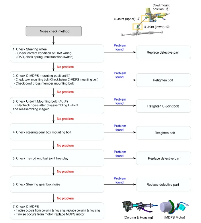
| Case 1 | Case 2 | Case 3 |
|
|
|
| Multifunction switch noise | Clock spring noise | DAB / Wire noise |
| Retighten the bolt | Replace clock spring | Rearrange and replace DAB |
| Case 4 | Case 5 | Case 6 |
|
|
|
| Multifunction switch noise | MB nut mount defect | M10 nut mount defect |
| Replace multifunction switch | Retighten nut | Retighten nut |
| Case 7 | Case 8 |
|
|
| Cowl top bolt mount defect | Cowl bar nut mount defect |
| Retighten cowl top bolt | Replace clock spring |

• Failure occurs due to internal damage because of the drop of and shock and excessive external force on the new partial component.→ Be cautious of shock on the partial component and replace the damaged part (due to drop, etc.) with a new one.
• When fastening the steering, excessive impact may result in twisting the center point of the torque sensor.
• When removing/installing the connector the wiring may be damaged (deformed) by excessive external force.
• Be cautious when storing and replacing the partial components under the abnormal temperature and humidity conditions.
MDPS Motor
1.Disconnect the battery negative cable and wait for at least three minutes before beginning work.
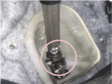
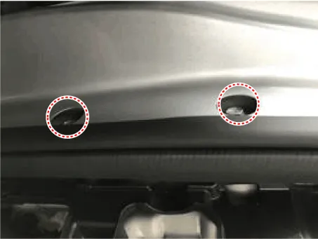
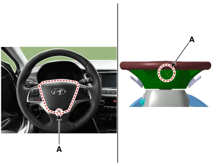
2.Put a flat tool (Ø4mm) into a guide hole located in the bottom of steering wheel and press a spring.


• When put a tool into a hole, make sure not to damage an airbag cusion by a tool.
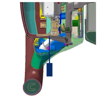
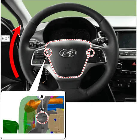
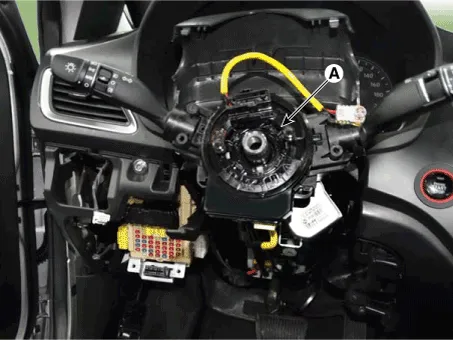
3.Turn a steering wheel anti-clockwise, so make a guide hole (A) shown on the rightside.Put a tool into a hole (A) and bend back a fixed DAB spring.Make sure to pull DAB cover when bend back the spring.

• Pull the DAB cover when disengaging the DAB spring because the DAB does not pop up automatically.
4.Turn a steering wheel clockwise. Put a tool into a hole (A) and bend back a fixed DAB spring. Make sure to pull DAB cover.


• Be careful not to put a tool into a wrong hole.
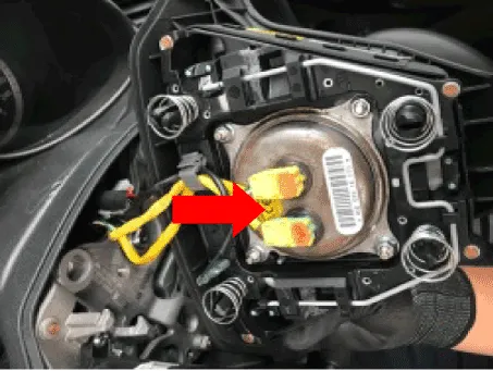
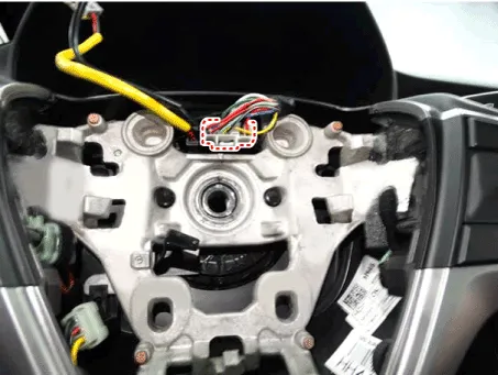
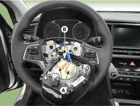
5.Release the connector locking pin, then disconnect the driver airbag module connector (A) and horn connector (B).


• The removed airbag module should be stored in a clean, dry place with the pad cover facing up.
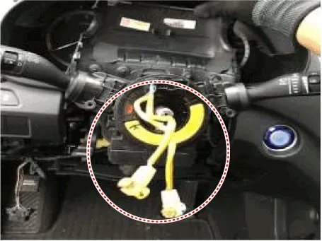
6.Disconnect the clock spring connector.
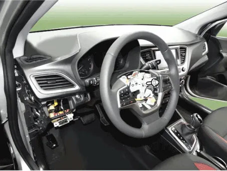
7.Remove the steering wheel by loosening the lock bolt (A).

8.Remove the steering column upper shroud (A).

9.Loosen the screw and then remove the lower shroud.

10.Disconnect the connector.

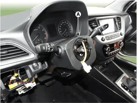
11.Remove the clock spring (A).

12.Disconnect the multifunction switch connector.
13.Loosen the screw and then remove the multifunction switch.
14.Remove the crash pad lower panel.(Refer to Body - "Crash Pad")
15.Remove the fixed clip and then remove the wiring from the steering column.

16.Disconnect MDPS ECU connector.
17.Remove the shower duct.
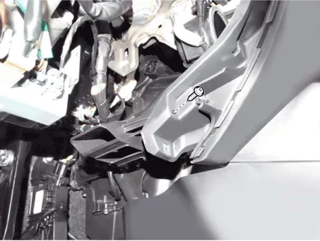
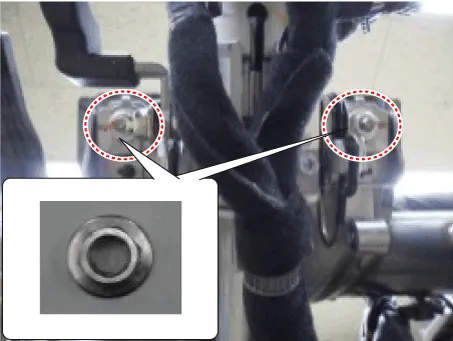
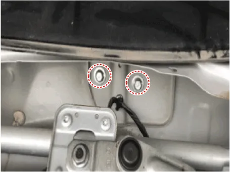
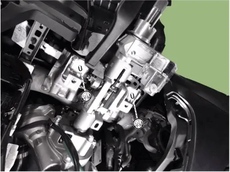
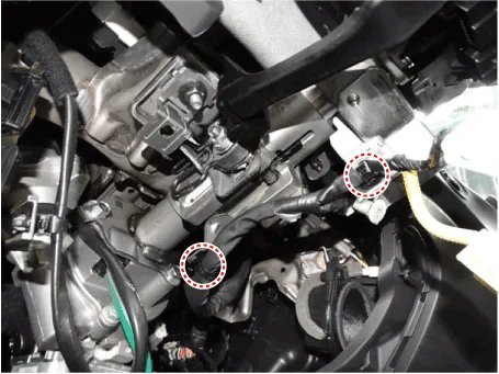
18.Remove the steering column & EPS unit assembly by loosening the mounting bolt and nuts.
Tightening torque Nut : 25.0 - 29.4 N.m (2.5 - 3.0 kgf.m, 14.5 - 21.7 lb-ft)Bolt : 44.1 - 49.0 N.m (4.5 - 5.0 kgf.m, 32.5 - 36.2 lb-ft)
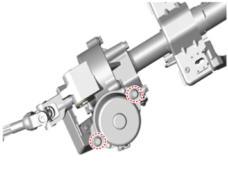
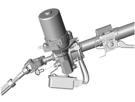
19.Remove the motor by loosening the bolts and then replace the new one.
Tightening torque :14.7 - 21.6 N.m (2.5 - 3.0 kgf.m, 18.1 - 21.7 lb-ft)
20.Install in the reverse order of removal.
21.Conduct the "ASP Calibration" and "EPS Type Recognition" by GDS.(Refer to MDPS motor - "Diagnosis with GDS ")
22.Remove the DTC.
23.Turn off the IGN switch and wait for 20 seconds or more. Then check the operation after starting the engine.
– Steering- angle sensor detects the steering angle and steering angle speed. Steering angle and steering angle speed are used for steering wheel damping and return controls in addition to providing assistance torque.

• You can use a scan tool to (GDS) check if the battery voltage is proper before perform the "ASP Calibration".
• Make sure that no connector engaged to the vehicle or scan tool is disconnected during the "ASP Calibration".
• Once the "ASP Calibration" is complete, turn off the IG switch and wait for 10 seconds or more before starting the engine to check the operation.
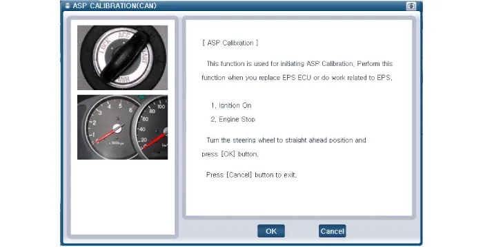
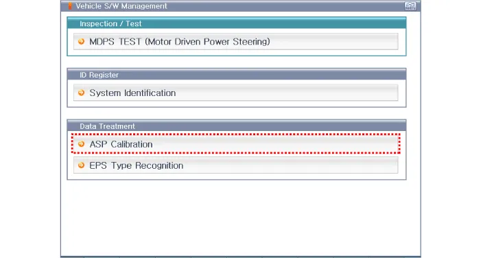
ASP Calibration procedures
1.Connect self - diagnosis connector (16pins) located in the lower of driver side crash pad to self - diagnosis device.
2.Turn the self - diagnosis device after key is ON.
3.Turn the steering wheel to straight ahead position.
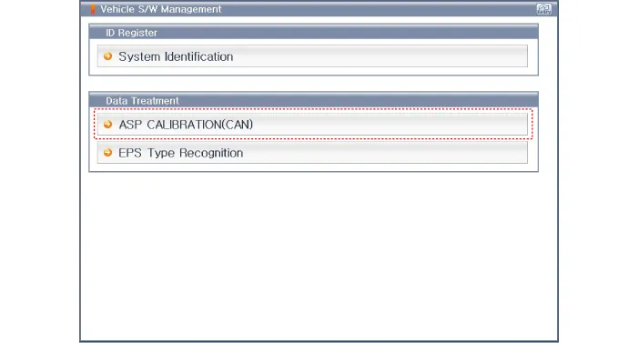
4.After Selecting the "vehicle model" and "system", select the "ASP Calibration" on GDS vehicle selection screen.

5.Remove the DTC.
6.Turn off the IG switch and wait for 10 seconds or more before starting the engine. And then make sure that MDPS works properly.
MDPS Control Unit
1.Disconnect the battery negative cable from the battery and then wait for at least 30 seconds.
2.Remove the crash pad lower panel.(Refer to Body - "Crash Pad Lower Panel")
3.Disconnect MDPS ECU connector.
4.Loosen the MDPS ECU bracket bolts and then remove the MDPS ECU.
ASP Calibration
– Steering- angle sensor detects the steering angle and steering angle speed. Steering angle and steering angle speed are used for steering wheel damping and return controls in addition to providing assistance torque.

• You can use a scan tool to (GDS) check if the battery voltage is proper before perform the "ASP Calibration".
• Make sure that no connector engaged to the vehicle or scan tool is disconnected during the "ASP Calibration".
• Once the "ASP Calibration" is complete, turn off the IG switch and wait for 10 seconds or more before starting the engine to check the operation.
1.Connect self - diagnosis connector (16pins) located in the lower of driver side crash pad to self - diagnosis device.
2.Turn the self - diagnosis device after key is ON.
3.Turn the steering wheel to straight ahead position.
4.After Selecting the "vehicle model" and "system", select the "ASP Calibration" on GDS vehicle selection screen.

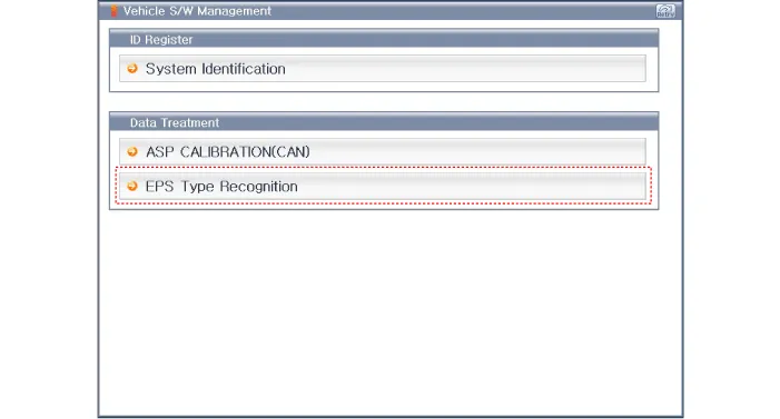
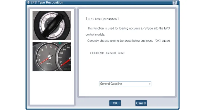
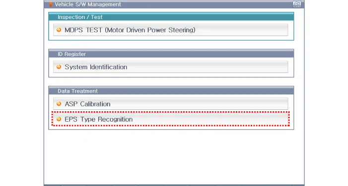
EPS Type Recognition

• When missing the EPS Type Recognition, occure a problem with motor driven power steering performance.

• You can use a scan tool to (GDS) check if the battery voltage is proper before perform the "EPS Type Recognition".
• Make sure that no connector engaged to the vehicle or scan tool is disconnected during the "EPS Type Recognition".
• Once the "EPS Type Recognition" is complete, turn off the IG switch and wait for 10 seconds or more before starting the engine to check the operation.
1.Connect self - diagnosis connector (16pins) located in the lower of driver side crash pad to self - diagnosis device.
2.Turn the self - diagnosis device after key is ON.
3.Turn the steering wheel to straight ahead position.
4.After Selecting the "vehicle model" and "system", select the "EPS Type Recognition" on GDS vehicle selection screen.
5.Remove the DTC.
6.Turn off the IG switch and wait for 10 seconds or more before starting the engine. And then make sure that MDPS works properly.
MDPS Column and Housing
1.Remove the MDPS assembly.(Refer to Steering System - "MDPS Assembly")
2.Remove the MDPS control unit.(Refer to Steering System - "MDPS Control Unit")
3.Remove the MDPS motor.(Refer to Steering System - "MDPS Motor")
1.Install in the reverse order of removal.
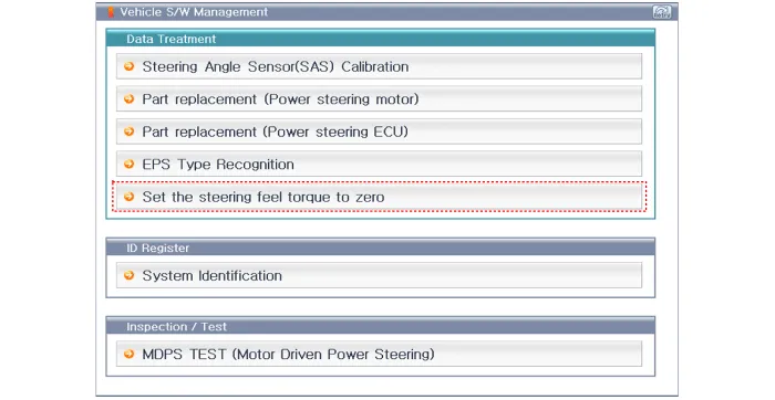
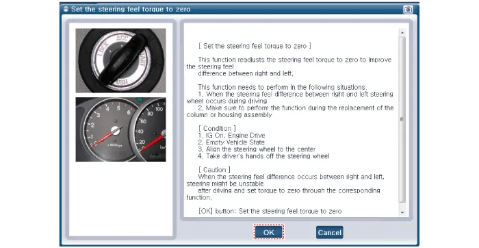
2.Perform "set the steering feel torque to zero" using the GDS.
3.Conduct the "ASP Calibration" by GDS.(Refer to MDPS Assembly - "Diagnosis with GDS")
4.Conduct the "EPS Type Recognition" by GDS.(Refer to MDPS Assembly - "Diagnosis with GDS")
5.Check the DTC.
6.Turn off the IGN switch and wait for 20 seconds or more. Then check the operation after starting the engine.
MDPS Assembly
1.Disconnect the battery negative cable and wait for at least three minutes before beginning work.
2.Put a flat tool (Ø4mm) into a guide hole located in the bottom of steering wheel and press a spring.


• When put a tool into a hole, make sure not to damage an airbag cusion by a tool.
3.Turn a steering wheel anti-clockwise, so make a guide hole (A) shown on the rightside. Put a tool into a hole (A) and bend back a fixed DAB spring. Make sure to pull DAB cover when bend back the spring.


• Pull the DAB cover when disengaging the DAB spring because the DAB does not pop up automatically.
4.Turn a steering wheel clockwise. Put a tool into a hole (A) and bend back a fixed DAB spring. Make sure to pull DAB cover.


• Be careful not to put a tool into a wrong hole.
5.Release the connector locking pin, then disconnect the driver airbag module connector (A) and horn connector (B).

• The removed airbag module should be stored in a clean, dry place with the pad cover facing up.
6.Disconnect the clock spring connector.

7.Remove the steering wheel by loosening the lock bolt (A).
8.Remove the steering column upper shroud (A).
9.Loosen the screw and then remove the lower shroud.
10.Disconnect the connector.
11.Remove the clock spring (A).
12.Disconnect the multifunction switch connector.


13.Loosen the screw and then remove the multifunction switch.

14.Remove the crash pad lower panel.(Refer to Body - "Crash Pad")
15.Remove the fixed clip and then remove the wiring from the steering column.
16.Disconnect MDPS ECU connector.

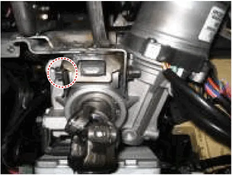
17.Loosen the bolt (A) and then disconnect the universal joint assembly from the pinion of the steering gear box.
Tightening torque : M8 BOLT : 32.4 - 37.3 N.m (3.3 - 3.8 kgf.m, 23.9 - 27.5 lb-ft)M10 BOLT : 49.0 - 58.8 N.m (5.0 - 6.0 kgf.m, 36.2 - 43.4 lb-ft)
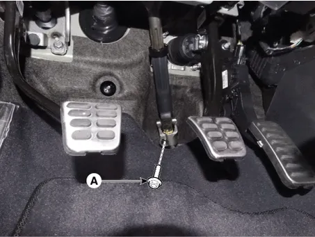

• Do not reuse the bolt.
• Lock the steering wheel in the straight ahead position to prevent the damage of the clock spring inner cable.
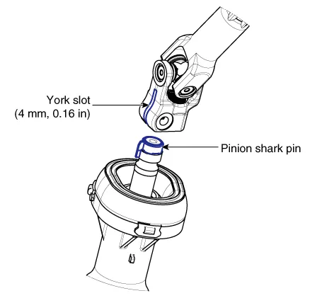
• When assembling, insert the shark pin into the universal joint york slot as the illustration below.
18.Remove the shower duct.

19.Remove the steering column & EPS unit assembly by loosening the mounting bolt and nuts.
Tightening torque Nut : 25.0 - 29.4 N.m (2.5 - 3.0 kgf.m, 14.5 - 21.7 lb-ft)Bolt : 44.1 - 49.0 N.m (4.5 - 5.0 kgf.m, 32.5 - 36.2 lb-ft)


1.Loosen the bolt (A) and then disconnect the universal joint assembly from the steering column assembly.
Tightening torque : 49.0 - 58.8 N.m (5.0 - 6.0 kgf.m, 39.8 - 43.4 lb-ft)
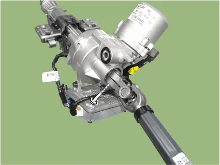

• Do not reuse the universal joint bolt.
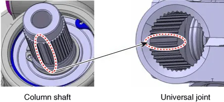
• When assembling, match the gear teeth as the below illustration.
2.To reassembly, reverse the disassembly procedure.
3.Reassembly is the reverse of the disassembly.
1.To install, reverse the removal procedure.
2.Connect self-diagnosis connector(16pins) located in the lower of driver side crash pad to self-diagnosis devic.
3.Conduct the "ASP Calibration".
4.Conduct the "EPS Type Recognition".
Steering Gear Box
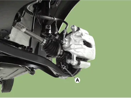
1.Loosen the wheel nuts slightly.Raise the vehicle, and make sure it is securely supported.
2.Remove the front wheel and tire (A) from the front hub.
Tightening torque :107.9 - 127.5 N.m (11.0 - 13.0 kgf.m, 79.6 - 94.0 lb-ft)
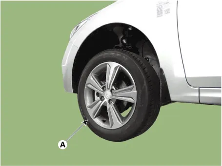

• Be careful not to damage the hub bolts when removing the front wheel and tire.
3.Disconnect the stabilizer link with the front strut assembly after loosening the nut (A).
Tightening torque :98.1 - 117.7 N.m (10.0 - 12.0 kgf.m, 72.3 - 86.8 lb-ft)

4.Remove the tie rod end ball joint.
(1)Remove the split pin (C).
(2)Loosen the nut (B).
(3)Using SST(09568-1S100), separate the ball joint (A) from the knuckle.
Tightening torque :24.5-34.3 N.m (2.5 - 3.5 kgf.m, 18.1 - 25.3 lb-ft)
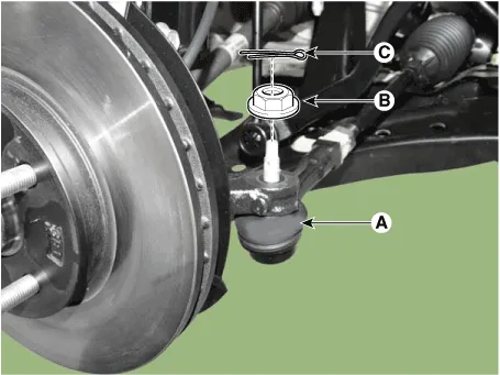
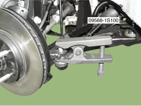

• Do not reuse the split pin (C).
5.Loosen the lower arm nut (A) and then remove the lower arm ball joint by using SST(09568-1S100).
Tightening torque : 58.8 - 70.6 N.m (6.0 - 7.2 kgf.m, 43.4 - 52.1 lb-ft)
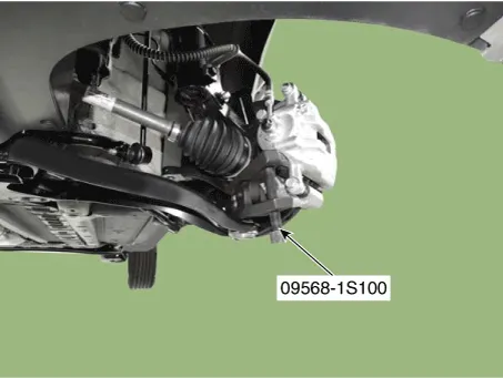

• Do not reuse the lower arm lock nut (A).
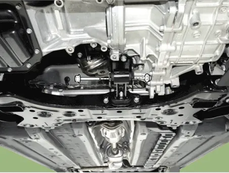
6.Loosen the bolt (A) and then disconnect the universal joint assembly from the pinion of the steering gear box.
Tightening torque : M8 BOLT : 32.4 - 37.3 N.m (3.3 - 3.8 kgf.m, 23.9 - 27.5 lb-ft)M10 BOLT : 49.0 - 58.8 N.m (5.0 - 6.0 kgf.m, 36.2 - 43.4 lb-ft)


• Do not reuse the bolt.
• Lock the steering wheel in the straight ahead position to prevent the damage of the clock spring inner cable.
• When assembling, insert the shark pin into the universal joint york slot as the illustration below.

7.Remove the roll rod stopper by loosening the bolt and nut.
Tightening torque :107.9 - 127.5 N.m (11.0 - 13.0 kgf.m, 79.6 - 94.0 lb-ft)
8.Remove the muffler rubber hanger (A).
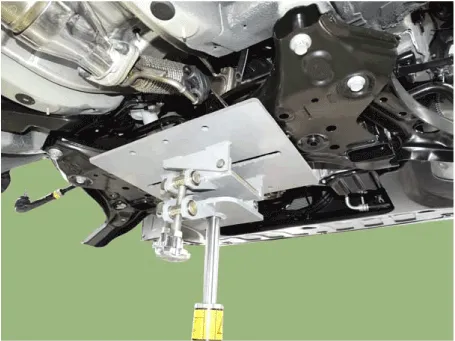
9.Remove the subframe by loosening the mounting bolts and nuts.
Tightening torque Sub frame mounting bolts and nut : 156.9 - 176.5 N.m (16.0 - 18.0 kgf.m, 115.7 - 130.2 b-ft)


• Set a transmission jack for safety.

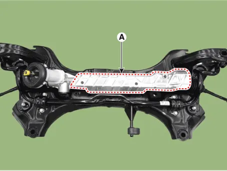
10.Remove the protector (A).
Tightening torque : 6.9 - 10.8 N.m (0.7 - 1.1 kgf.m, 5.1 - 8.0 lb-ft)
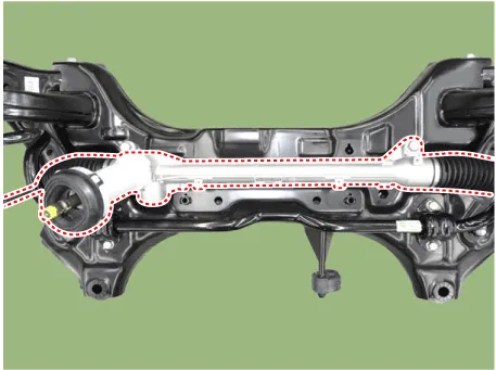
11.Remove the steering gearbox from the front sub frame by loosening the mounting bolts.
Tightening torque : 88.2 - 107.8 N.m (9.0 - 11.0 kgf.m, 65.0 - 79.5 lb-ft)
12.To install, reverse the removal procedure.
13.Check the front alignment.(Refer to Suspension System - "Front Alignment")

• Do not disassembly the steering gear box.
• If disassembly the steering gear box, the quality (Noise / cleanliness / functions) is not guaranteed.
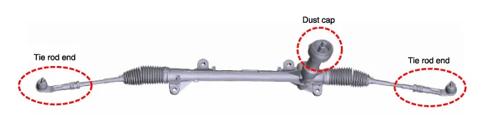
Tie rod end
1.Remove the tie rod end after loosening the nut.
Tightening torque :49.0 - 53.9 N.m (5.0 - 5.5 kgf.m, 36.2 - 39.8 lb-ft)
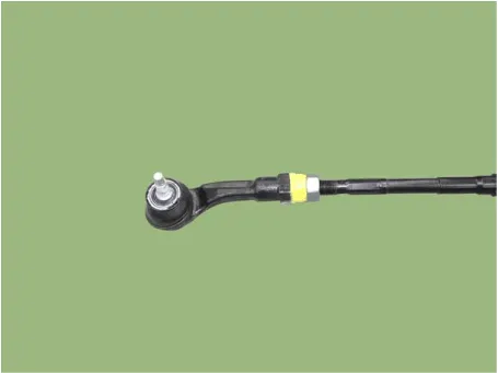

• Before removing the tie rod end, note by measuring the length of the thread or marked with paint.
2.Replace with new parts.
3.Check the alignment.(Refer to Tires/ Wheels - "Alignment")


Other information:
Hyundai Accent (HC) (2017 - 2022) Service Manual: Front Disc Brake
- Components 1. Caliper body2. Guide rod pin3. Guide rod boot4. Caliper carrier5. Inner pad shim 6. Brake pad7. Pad retainer8. Pad return spring - Removal 1.Loosen the wheel nuts slightly.Raise the vehicle, and make sure it is securely supported. 2.Remove the front wheel and tire (A) from the front hub.Tightening torque :107.9 - 127.5 N.Hyundai Accent (HC) (2017 - 2022) Service Manual: If You Have a Flat Tire
WARNING Changing a tire can be dangerous. Follow the instructions in this section when changing a tire to reduce the risk of serious injury or death. Whenever possible, change the tire on a firm, level surface away from traffic. CAUTION Be careful as you use the jack handle to stay clear of the flat end. The flat end has sharp edges that could cause cuts.
Contents
- Description and Operation
- Schematic Diagrams
- Components and Components Location
- Repair procedures
- MDPS Motor
- MDPS Control Unit
- MDPS Column and Housing
- MDPS Assembly
- Steering Gear Box
Categories
- Manuals Home
- Hyundai Accent Owners Manual
- Hyundai Accent Service Manual
- Questions & Answers
- Video Guides
- Useful Resources
- New on site
- Most important about car
- Privacy Policy

0.0065