Hyundai Accent (HC): Steering System / Steering wheel
Contents:
Components and Components Location
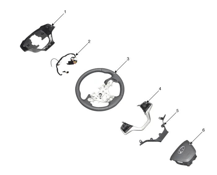
1. Lower cover
2. Wiring
3. Steering wheel
4. Remote control swtich
5. Upper cover
6. Driver airbag module
Repair procedures
1.Disconnect the battery negative cable and wait for at least three minutes before beginning work.
2.Put a flat tool (├ś4mm) into a guide hole located in the bottom of steering wheel and press a spring.
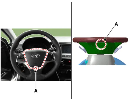

ŌĆó When put a tool into a hole, make sure not to damage an airbag cusion by a tool.
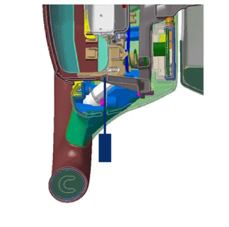
3.Turn a steering wheel anti-clockwise, so make a guide hole (A) shown on the rightside. Put a tool into a hole (A) and bend back a fixed DAB spring. Make sure to pull DAB cover when bend back the spring.

ŌĆó Pull the DAB cover when disengaging the DAB spring because the DAB does not pop up automatically.
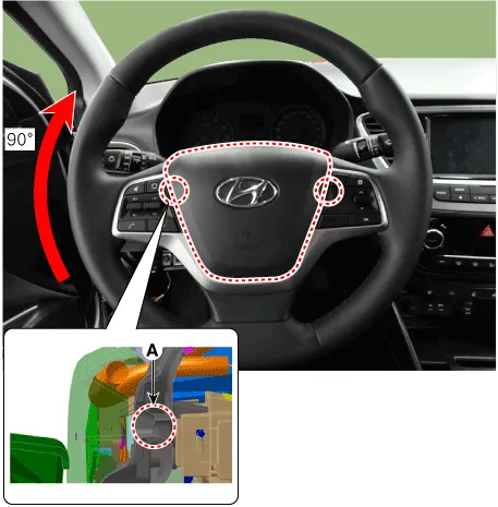
4.Turn a steering wheel clockwise. Put a tool into a hole (A) and bend back a fixed DAB spring. Make sure to pull DAB cover.


ŌĆó Be careful not to put a tool into a wrong hole.
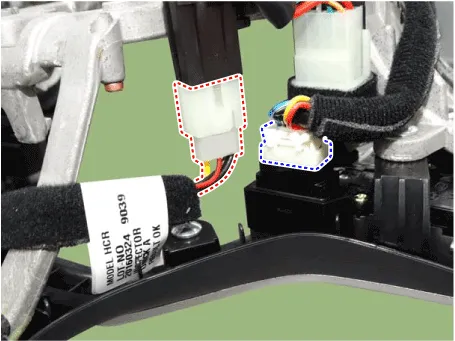
5.Release the connector locking pin, then disconnect the driver airbag module connector (A) and horn connector (B).
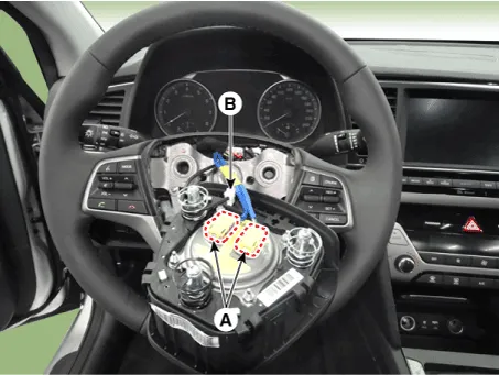

ŌĆó The removed airbag module should be stored in a clean, dry place with the pad cover facing up.
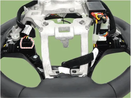
6.Disconnect the clock spring connector.
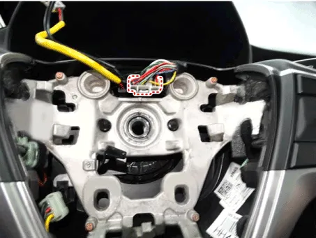
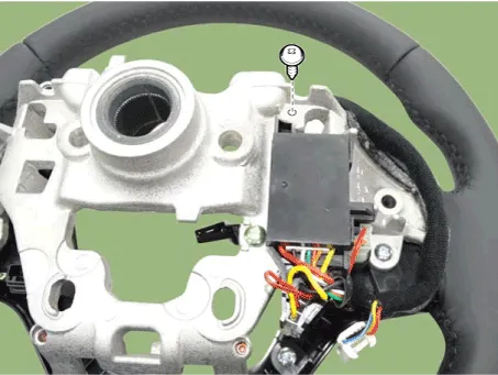
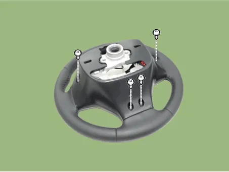
7.Remove the steering wheel by loosening the lock bolt (A).
Tightening torque : 44.1 - 49.0 N.m (4.5 - 5.0 kgf.m, 32.5 - 36.2 lb-ft)
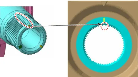
8.Install in the reverse order of removal.

ŌĆó Do not reuse the steering lock bolt.
ŌĆó When assembling, match the gear teeth as the below illustration.
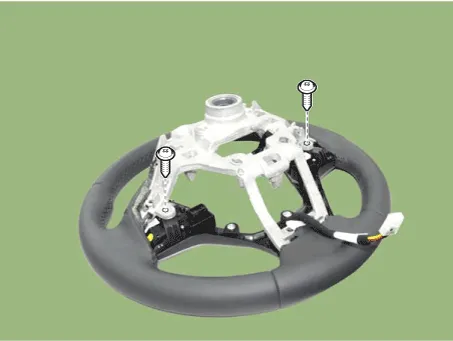
1.Loosen the screw and then remove the lower cover.

2.Disconnect the remote control switch connector.

3.Remove the control box by loosening the screw.
4.Remove the remote control switch by loosening the screw.
5.Remove the upper cover by loosening the screw.
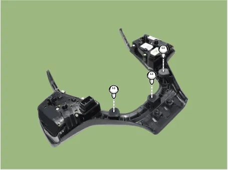
6.To reassembly, reverse in the disassembly procedure.
Heated Steering wheel
Heated steering wheel switch
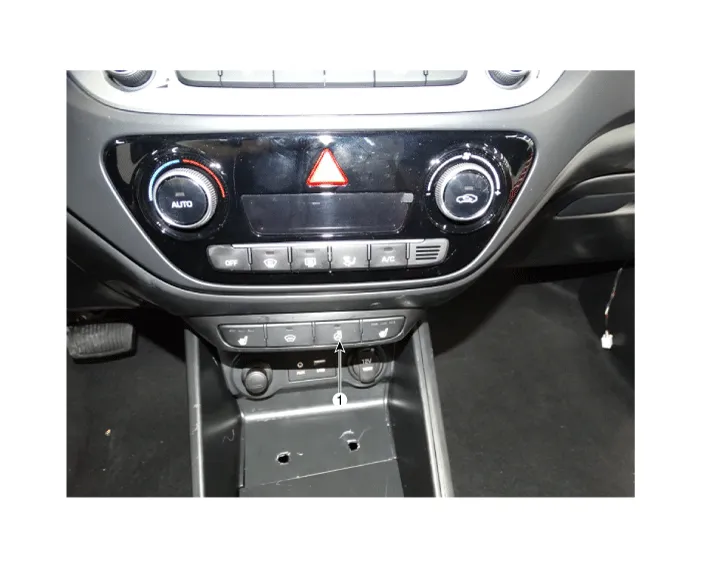
1. Heated steering wheel switch
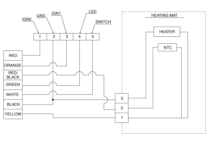
Heated steering wheel control unit

1. Heated steering wheel control unit
Heated steering wheel pad
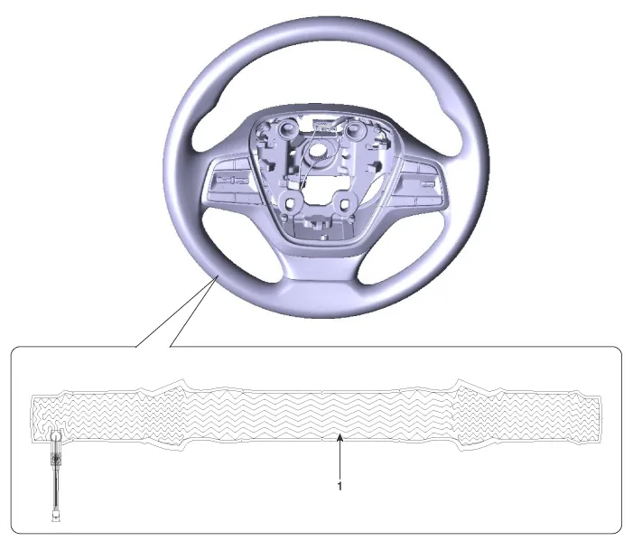
1. Heated steering wheel control pad
ŌĆó For the convenience of drivers during the winter, exothermic paint is applied to the surface of the steering wheel to generate heat when it is gripped.
| Item | Specification |
| Voltage | 13.5 V |
| Heated pad resistance | 1.7 ┬▒ 0.2 ╬® (22┬░C) |
| NTC resistance | 4.3 k╬® ┬▒ 10% (22┬░C) |
Heated steering wheel control unit
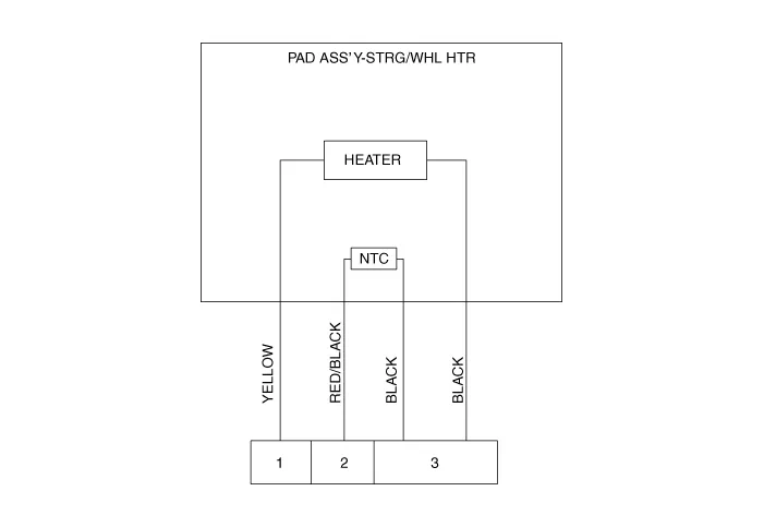
Heated steering wheel pad
Heated steering wheel switch

Heated steering wheel control unit
Heated steering wheel pad

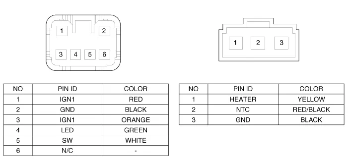
| Housing | Pin | Function | Wire color |
| Pad | 1 | HEATER | YELLOW |
| 2 | NTC+ | RED/BLACK | |
| 3 | Ground (Heater) | BLACK | |
| Ground (NTC-) |
Heated steering wheel switch
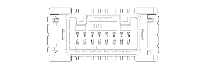
| Pin | Function |
| 10 | Steering wheel heat signal |
| 11 | Steering wheel heat IND |
| 16 | Ground |
Heated steering wheel switch
1.Disconnect the negative (-) batttery terminal.
2.Remove the floor console assembly.(Refer to Body - "Floor Console Assembly")
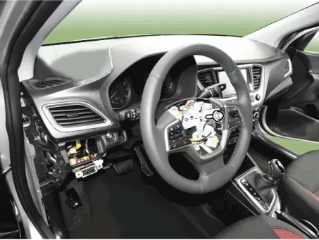
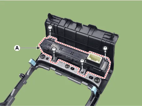
3.Remove the heated steering wheel switch (A) after loosening the screws.
4.To install, reverse the removal procedure.
Heated steering wheel control unit
1.Remove the steering wheel.(Refer to Steering System - "Steering Wheel")
2.Loosen the screw and then remove the lower cover.
3.Disconnect the remote control switch connector.

4.Remove the control box by loosening the screw.

5.To install, reverse the removal procedure.


Other information:
Hyundai Accent (HC) (2017 - 2022) Service Manual: Crankshaft
- Disassembly ŌĆó Use fender covers to avoid damaging painted surfaces. ŌĆó To avoid damage, unplug the wiring connectors carefully while holding the connector portion. ŌĆó Mark all wiring connector and hoses to avoid misconnection. ŌĆó To release the fuel system pressure before removing the engine assembly, start the engine without fuel pump relay.Some Hyundai Accent models use a Smart Key, which you can use to lock or unlock a door (and trunk) and start the engine. For best performance, keep the Smart Key close to you and avoid storing it near strong electromagnetic sources. 1. Door Lock 2. Door Unlock 3. Trunk Unlock 4. Panic Locking To lock your Hyundai Accent using the Smart Key system: 1.
Contents
Categories
- Manuals Home
- Hyundai Accent Owners Manual
- Hyundai Accent Service Manual
- Questions & Answers
- Video Guides
- Useful Resources
- New on site
- Most important about car
- Privacy Policy

0.0063