Hyundai Accent (HC): Brake System (ABS/ESC) / Parking Brake System
Contents:
- Components and Components Location
- Parking Brake Lever
- Parking Brake Switch
- Parking Brake Cable
- Parking Brake Assembly
Components and Components Location
[Disc Type]
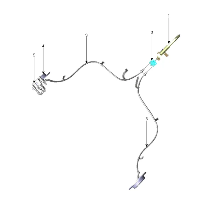
1. Parking brake lever
2. Equalizer assembly
3. Parking brake cable
4. Brake disc
5. Brake caliper
[Drum Type]
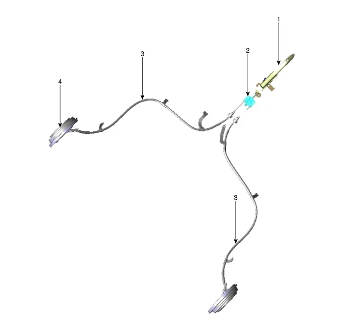
1. Parking brake lever
2. Equalizer assembly
3. Parking brake cable
4. Drum brake
Parking Brake Lever
1.Disconnect the negative (-) battery cable.
2.Release the parking brake.
3.Remove the floor console assembly.(Refer to Body - "Floor Console")
4.Disconnect the connector of parking brake switch.

5.Remove the parking brake switch.
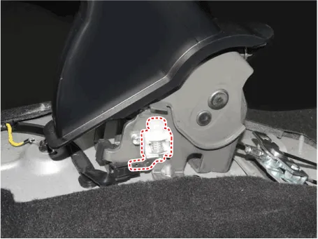
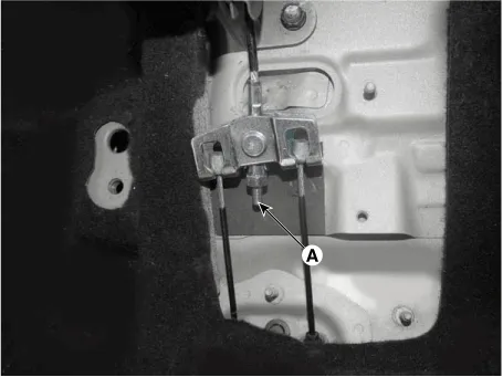
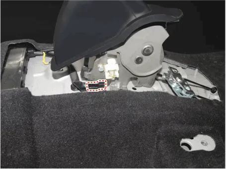
6.Remove the parking brake cable after loosening the nut (A).
7.Remove the parking brake lever assembly after loosening the bolts.
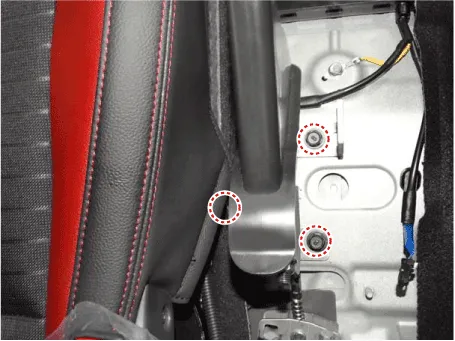
1.Install the parking brake lever assembly.
Tightening torque :19.6 - 29.4 N.m (2.0 - 3.0 kgf.m, 14.5 - 21.7 lb-ft)
Remove the parking brake lever assembly after loosening the bolts.

2.Install the parking brake cable.

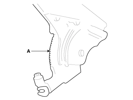
3.Apply a coating of the specified grease to each sliding parts (A) of the ratchet plate or the ratchet pawl.
Specified grease :CASMOLY 623
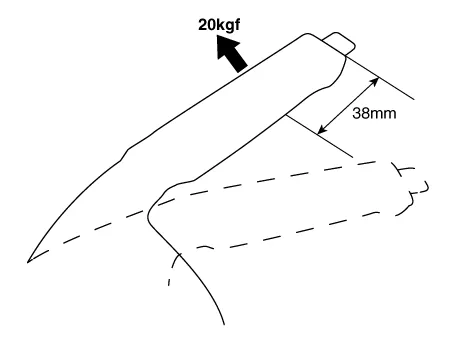
4.Install the parking brake cable adjuster, then adjust the parking brake lever stroke by turning adjusting nut (A).
Parking brake lever stroke :5 - 7 clicks (Pull the lever with 196N (20 kgf, 44 lbf))

1.Remove the floor console assembly. (Refer to Body - "Floor Console")
2.Bring the brake pads in their operating position by pressing the brake pedal down several times until there is resistance.
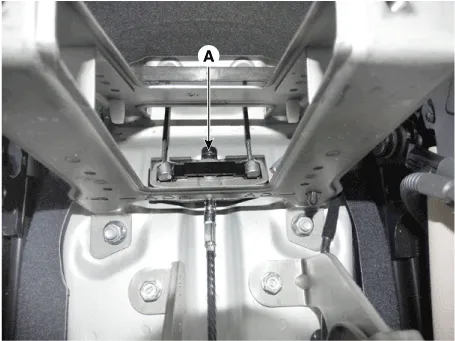
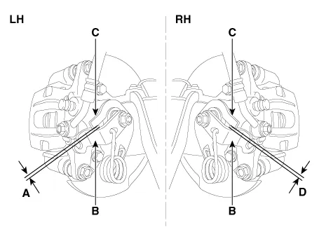
3.Tension the parking brake cable by tightening the adjusting nut, until the operating levers on both calipers lift from the stop, up to a distance of (A) and (D) between operating lever (B) and stopper (C).
Distance (A + D) : Max. 3 mm (0.12 in)

4.adjust the parking brake lever stroke by turning adjusting nut (A).
5.Release the parking brake lever fully, and check that parking brakes do not drag when the rear wheels are turned. Readjust if necessary.
6.Install the floor console. (Refer to Body - "Floor Console")
7.Make sure that the parking brakes are fully applied when the parking brake lever is pulled up fully.
Parking Brake Switch
1.Disconnect the negative (-) battery cable.
2.Release the parking brake.
3.Remove the floor console assembly. (Refer to Body - "Floor Console")
4.Disconnect the connector of parking brake switch.
5.Remove the parking brake switch.

Parking Brake Cable
1.Disconnect the negative (-) battery cable.
2.Release the parking brake.
3.Remove the floor console assembly. (Refer to Body - "Floor Console")
4.Disconnect the connector of parking brake switch.

5.Remove the parking brake switch.

6.Remove the parking brake cable after loosening the nut (A).

7.Loosen the wheel nuts slightly.Raise the vehicle, and make sure it is securely supported.
8.Remove the rear wheel and tire (A) from front hub.
Tightening torque :107.9 - 127.5 N.m (11.0 - 13.0 kgf.m, 79.6 - 94.0 lb-ft)


• Be careful not to damage the hub bolts when removing the rear wheel and tire.
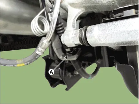
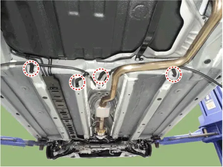
9.Remove the parking brake cable fixed clip (A).
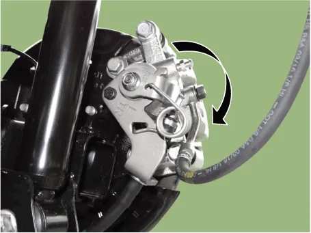
10.Pull the operation lever as a arrow below in order to loosen the cable and then remove the parking cable.
11.Loosen the mounting bolt and then remove the parking brake cable bracket.
Tightening torque :8.8 - 13.7 N.m(0.9 - 1.4 kgf.m, 6.5 - 10.1 lb-ft)

12.Loosne the parking brake cable mouting bolts and then remove the cable.
Tightening torque :8.8 - 13.7 N.m(0.9 - 1.4 kgf.m, 6.5 - 10.1 lb-ft)

13.To install, reverse the removal procedure.
1.Disconnect the negative (-) battery cable.
2.Release the parking brake.
3.Remove the floor console assembly. (Refer to Body - "Floor Console")
4.Disconnect the connector (A) of parking brake switch.

5.Remove the parking brake switch.

6.Remove the parking brake cable after loosening the nut (A).

7.Loosen the wheel nuts slightly.Raise the vehicle, and make sure it is securely supported.
8.Remove the rear wheel and tire (A) from front hub.
Tightening torque :107.9 - 127.5 N.m (11.0 - 13.0 kgf.m, 79.6 - 94.0 lb-ft)


• Be careful not to damage the hub bolts when removing the rear wheel and tire.
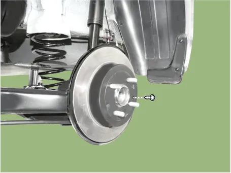
9.Loosen the screws and then remove the brake disc.
Tightening torque :4.9 - 5.9 N.m (0.5 - 0.6 kgf.m, 3.6 - 4.3 lb-ft)

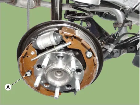
10.Remove the upper shoe return spring (A), lower shoe return spring (B), level pawl (C) and djuster assembly (D).

11.Remove the adjusting spring (A).
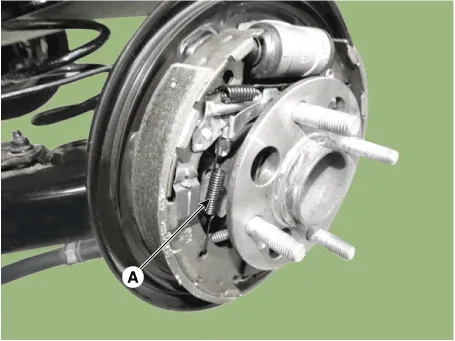
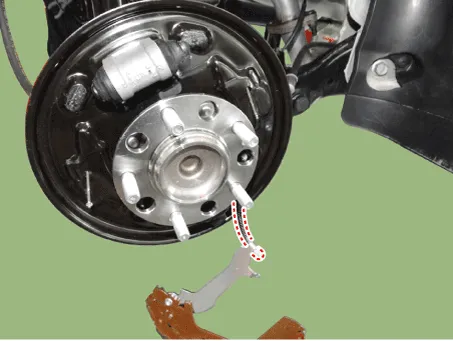
12.Remove the shoe hold assembly (A) and then remove the brake shoe.
13.Disconnect the parking cable.

14.Loosne the parking brake cable mouting bolts and then remove the cable.
Tightening torque :8.8 - 13.7 N.m (0.9 - 1.4 kgf.m, 6.5 - 10.1 lb-ft)
15.To install, reverse the removal procedure.

• Re- setting of the parking brake is necessary after overhauling the caliper body, or if the brake calipers, housing, parking brake cable or brake discs have been changed.
1.Remove the floor console to reach the adjusting nut.
2.Loosen the parking brake cable until both operating levers rest in fully off position.
3.Bring the brake pads in their operating position by pressing the brake pedal down several times until there is resistance.
4.Tension the parking brake cable by tightening the adjusting nut, until the operating levers on both calipers lift from the stop, up to a distance of (A) and (D) between operating lever (B) and stopper (C).
Distance (A + D) : Max. 3 mm (0.12 in)
5.Refit the floor console.
6.Parking brake lever in the car must be in fully loosened position.
7.If the handbrake cables where changed, actuate the parking brake a few times with maximum force to stretch the parking brake cables, and then control adjusting as above.
8.Check the wheels of their free operation.
9.Test drive.
1.Depress the brake pedal several times to set the self-adjusting brake.

• For Drum Brake type, shoe clearance is automatically adjusted by the adjuster and adjusting lever.
Parking Brake Assembly
1.Loosen the wheel nuts slightly.Raise the vehicle, and make sure it is securely supported.
2.Remove the rear wheel and tire (A) from front hub.
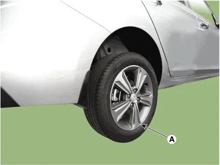

• Be careful not to damage the hub bolts when removing the rear wheel and tire.
3.Loosen the screws and then remove the brake disc.

4.Remove the upper shoe return spring (A), lower shoe return spring (B), level pawl (C) and djuster assembly (D).
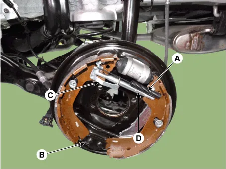
5.Remove the shoe hold assembly (A) and then remove the brake shoe.

6.Disconnect the parking cable.
7.To install, reverse the removal procedure.
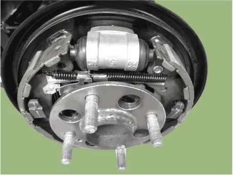
8.Adjust the rear brake shoe clearance.
9.Rotate the toothed wheel of adjuster by a screw driver until the disc is not moving, and then return it by 5~7 notches in the opposite direction.
10.Instll the drum.
Tightening torque :4.9 - 5.9 N.m (0.5 - 0.6 kgf.m, 3.6 - 4.3 lb-ft)
11.Install the rear wheel and tire (A).
Tightening torque :107.9 - 127.5 N.m (11.0 - 13.0 kgf.m, 79.6 - 94.0 lb-ft)


• Be careful not to damage the hub bolts when installing the rear wheel and tire.


Other information:
Hyundai Accent (HC) (2017 - 2022) Service Manual: Vehicle load limit
Two labels on your driver’s door sill show how much weight your Hyundai Accent was designed to carry: the Tire and Loading Information Label and the Certification Label. These labels help you confirm safe loading limits before you add passengers or cargo. Before loading your Hyundai Accent, familiarize yourself with the following terms for determining your vehicle’s weight ratings, based on the vehicle specifications and the Certification Label: Base Curb Weight This is the weight of the vehicle including a full tank of fuel and all standard equipment.
Contents
- Components and Components Location
- Parking Brake Lever
- Parking Brake Switch
- Parking Brake Cable
- Parking Brake Assembly
Categories
- Manuals Home
- Hyundai Accent Owners Manual
- Hyundai Accent Service Manual
- Questions & Answers
- Video Guides
- Useful Resources
- New on site
- Most important about car
- Privacy Policy

0.0063