Hyundai Accent (HC): Advanced Driver Assistance System (ADAS) / Parking Distance Warning (PDW)
Contents:
- Specifications
- Components and Components Location
- Description and Operation
- Parking Distance Warning (PDW) Sensor
Specifications
| Item | Specification | |
| Ultrasonic sensor | Voltage rating | DC 12 V |
| Detecting range | 30 cm - 120 cm | |
| Operation voltage | DC 9 - 16 V | |
| Operation current | MAX 350 mA | |
| Operation temperature | -30°C to +80°C | |
| Operation frequency | 48 ± 5 KHz | |
| Number of sensors | 4 (Left side, Left center, Right center, Right side) | |
Parking distance warning (PDW) control unit function is built in BCM (Body control unit).
Components and Components Location
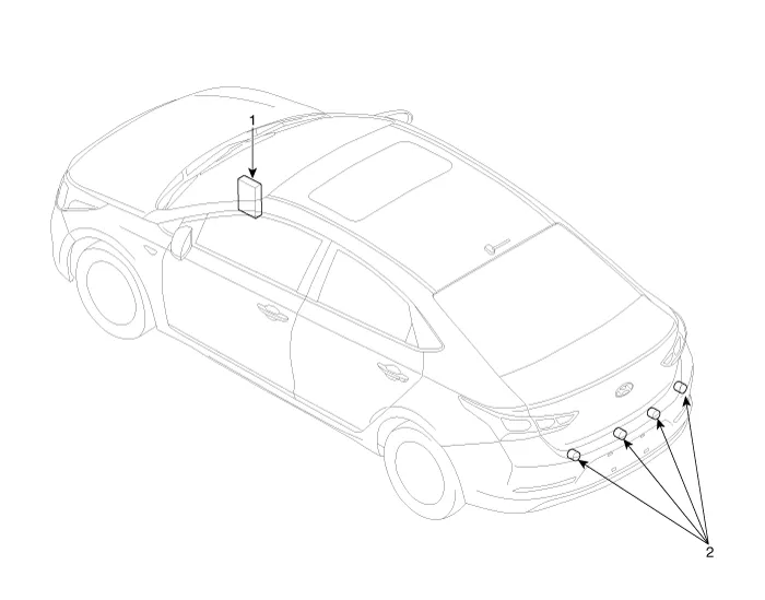
1. Body control unit (BCM)
2. Parking distance warning sensor
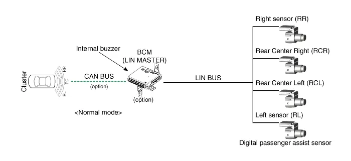
Description and Operation
• PDW consists of 8 sensors (front : 4 units, rear : 4 units) that are used to detect obstacles and transmit the result in three separate warning levels, the first, second and third to IBU via LIN communication.
• IBU decides the alarm level by the transmitted communication message from the slave sensors, then operates the buzzer or transmits the data for display.
Initial mode
1.System initializing time
– PDW-R : 500ms after IGN1+ initial R Gear
2.PDW recognizes LID and sets the sensor ID up during initialization.
3.PDW activates each sensor and then executes the diagnosis after finishing initialization of BCM.
4.PDW starting buzzer is normally worked, when sensor does not send an error message and after finishing error diagnosis.
5.If any failure is received from the any sensors, PDW starting buzzer does not work but the failure alarm is operated for a moment.If you have display option, warning sign is also shown on it.

6.IBU memorizes the completed initializing status of sensor.
Normal mode
1.PDW-F : Lin communication starts and keeps the routine after IGN1 ON+D gear + below 10 km/h. PDW-R : Lin communication starts and keeps the routine after IGN1 ON+R gear
2.After initializing, the routine starts at once without PDW starting warning sound.
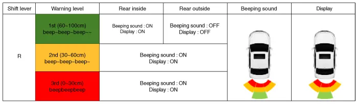
3.Alarms of obstacle consists of 3 level 1,2,3 step and 1,2 alarm sounds intermittently and 3 alarm sounds continuously. 1 level alarm doesn't exist in the front ultrasonic sensor.
4.In display, the data of each sensor is sent from IBU to display, for example cluster. CAN communication is used for transmission and maximum gateway time is 50ms.
5.The efficient vehicle speed of PDW operation is under 10Km/h.
6.Operation doesn't start or stops at gear N, P.
| Level | Distance range | Allowed range |
| 1 | Rear : 61 - 120 cm (24.02 - 47.2 in.) | ± 15 cm (5.90 in.) |
| 2 | 31 - 60 cm (12.20 - 23.62 in.) | ± 15 cm (5.90 in.) |
| 3 | 0 - 30 cm (0 - 11.81 in) | ± 10 cm (3.94 in.) |
*Measurement condition : PVC pipe - Diameter 75 mm (0.0394 in.), length 1 m (39.37 in.), at normal temperature
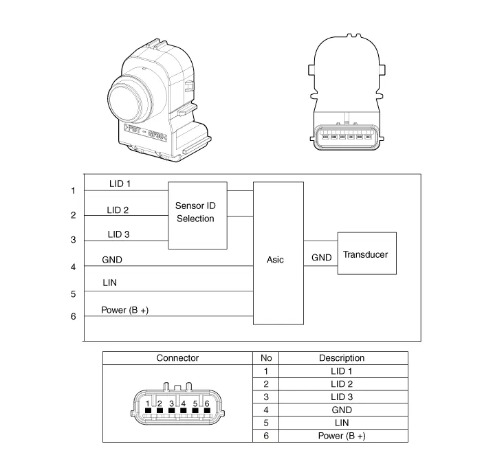
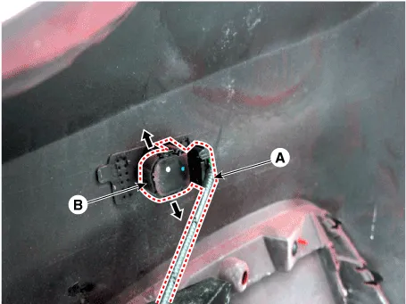
Parking Distance Warning (PDW) Sensor
1.Remove the bumper cover.(Refer to Body - "Front Bumper Cover")(Refer to Body - "Rear Bumper Cover")
2.Disconnect the connector (A) from the PDW sensor (B).
1.Install the PDW sensor.
2.Install the bumper cover.


Other information:
Hyundai Accent (HC) (2017 - 2022) Service Manual: Windshield defrosting and defogging
WARNING Windshield heating Do not use the or position during cooling operation in extremely humid weather. The difference between the temperature of the outside air and that of the windshield could cause the outer surface of the windshield to fog up, causing loss of visibility could cause an accident resulting in serious injury or death. In this case, set the mode selection knob or button to the position and fan speed control knob or button to a lower speed.Hyundai Accent (HC) (2017 - 2022) Service Manual: Tire Replacement
On the Hyundai Accent, a tire that wears evenly will eventually reveal the built-in tread wear indicators. These indicators appear as a solid, continuous band across the tread and confirm there is less than 2/32 inch (1.6 mm) of usable tread remaining. Replace the tire when this happens to help maintain safe braking performance, stable steering control, and reliable wet-weather traction.
Contents
- Specifications
- Components and Components Location
- Description and Operation
- Parking Distance Warning (PDW) Sensor
Categories
- Manuals Home
- Hyundai Accent Owners Manual
- Hyundai Accent Service Manual
- Questions & Answers
- Video Guides
- Useful Resources
- New on site
- Most important about car
- Privacy Policy

0.0102