
Hyundai Accent (HC): Advanced Driver Assistance System (ADAS) / Rear View Monitor (RVM)

Contents:

Components and Components Location

- Component Location

1. Rear view camera
2. AVN monitor


Schematic Diagrams
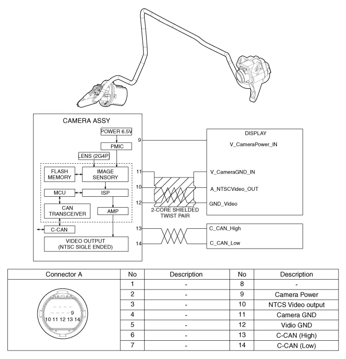
- Circuit Diagram

Description and Operation

- Description Rear view camera will activate when the backup light is ON with the ignition switch ON and the shift lever in the R position.This system is a supplemental system that shows behind the vehicle through the AV monitor or the ECM (Reverse Display Room Mirror) mirror while backing-up.


This system is a supplementary function only. It is the responsibility of the driver or always check the inside/ outside rear view mirror and the area behind the vehicle before and while backing up because there is a dead zone that can't see through the camera.

Repair procedures

- Removal

1.Disconnect the negative (-) battery terminal.

2.Remove the trunk trim.(Refer to Body - "Trunk Rid Trim")

3.Remove the trunk back panel.(Refer to Body - "Trunk back Panel")

4.Remove the rear center tail lamp.(Refer to Lighting System - "Rear Combination Lamp")

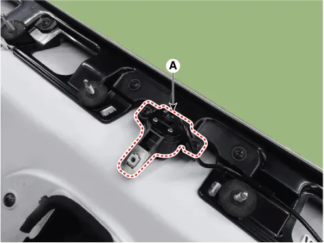
5.Loosen the mounting screw and then remove the camera (A).
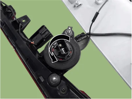
6.Remove the rear camera after turning in the counterclockwise direction.
- Installation

1.Install the rear view camera.

2.Install the and trunk back panel.

3.Install the and trunk rid trim.

4.Connect the negative (-) battery terminal.

Other information:

Hyundai Accent (HC) (2017 - 2022) Service Manual: Troubleshooting

- Basic Troubleshooting Basic Troubleshooting Guide Customer Problem Analysis Sheet Basic Inspection Procedure Measuring Condition Of Electronic Parts' Resistance The measured resistance at high temperature after vehicle running may be high or low. So all resistance must be measured at ambient temperature (20°C, 68°F), unless stated otherwise.

Hyundai Accent (HC) (2017 - 2022) Service Manual: Stop Lamp Switch

- Components 1. Brake pedal member assembly2. Stop lamp switch3. Brake pedal arm 4. Pedal pad - Schematic Diagram - System circuit diagram - Terminal function TerminalDescription 1IGN 2BS 3- 4B+ 5BLS 6GND - Adjustment 1.Turn ignition switch OFF and disconnect the negative (-) battery cable. 2.Remove the lower crash pad.

Contents

Categories

 
Copyright © 2026
0.01