Hyundai Accent (HC): Body Electrical System / Keyless Entry And Burglar Alarm
Contents:
- Specifications
- Components and Components Location
- Description and Operation
- Repair procedures
- Transmitter
Specifications
| Item | Specification |
| Power source | 3V |
| Operating temperature | -10¬įC to +60¬įC (14¬įF to +140¬įF) |
| RF Modulation | FSK |
| LF Modulation | ASK |
| RF frequency | 134.2MHz |
| Battery | CR2032 |
| Transmissible distance | 10m or more |
| Life of battery | 2years or more (at 20 times per day) |
| Button number | 3 and 4 |
| Function | Door lock |
| Door unlock | |
| Trunk Unlock Button |
Components and Components Location
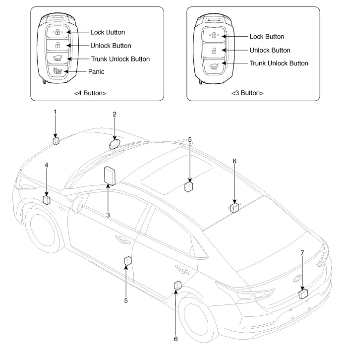
1. Hood switch
2. Burglar horn
3. Body Control Module (BCM)
4. Door lock / unlock buzzer
5. Front door lock actuator & switch
6. Rear door lock actuator & switch
7. Tailgate open switch
Description and Operation ➤
Repair procedures
1.Remove the front door trim.(Refer to Body - "Front Door Trim")
2.Remove the front door module.(Refer to Body - "Front Door Module")
3.Disconnect the connectors from the actuator.
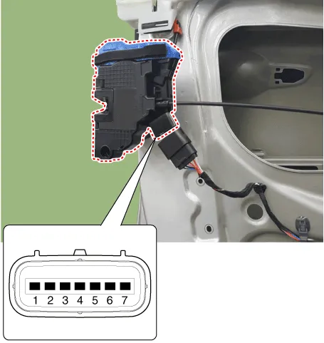
| No | Pin Information | |
| LH | RH | |
| 1 | Motor 1 | Lock / UnLock switch |
| 2 | Motor 2 | COM |
| 3 | - | Key Lock switch |
| 4 | Key Unlock switch | Key Unlock switch |
| 5 | Key Lock switch | - |
| 6 | COM | Motor 2 |
| 7 | Lock / UnLock switch | Motor 1 |
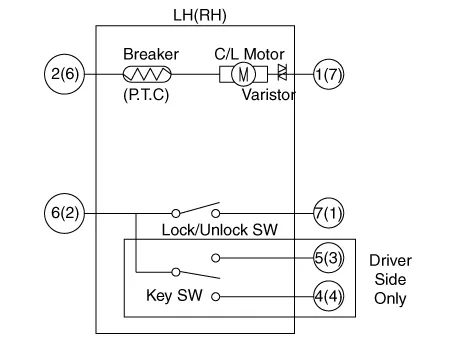
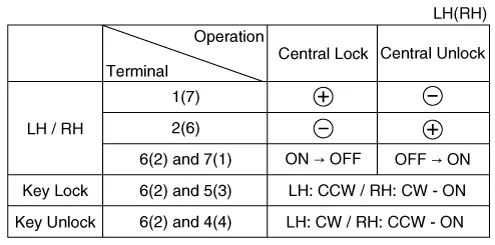
4.Check actuator operation by connecting power and ground according to the table. To prevent damage to the actuator, apply battery voltage only momentarily.
1.Remove the rear door trim.(Refer to Body - "Rear Door Trim")
2.Remove the rear latch.(Refer to Body - "Rear Door Latch")
3.Disconnect the connectors from the actuator.
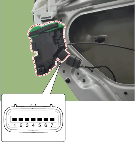
| No | Pin Information | |
| LH | RH | |
| 1 | Motor 1 | Lock / UnLock switch |
| 2 | Motor 2 | COM |
| 3 | - | - |
| 4 | - | - |
| 5 | - | - |
| 6 | COM | Motor 2 |
| 7 | Lock / UnLock switch | Motor 1 |
4.Check actuator operation by connecting power and ground according to the table. To prevent damage to the actuator, apply battery voltage only momentarily.


1.Remove the door switch (A) after loosening the screw and disconnecting the connector (B).
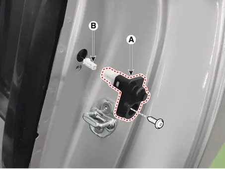
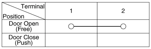
2.Check for continuity between the terminals in each switch position according to the table.

1.Remove the tailgate trim. (Refer to Body - "Tailgate Trim")
2.Disconnect the connector from the actuator.

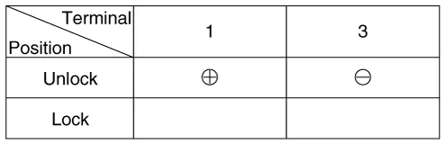
3.Check for continuity between the terminals in each switch position according to the table.

4.Check actuator operation by connecting power and ground according to the table. To prevent damage to the actuator, apply battery voltage only momentarily.
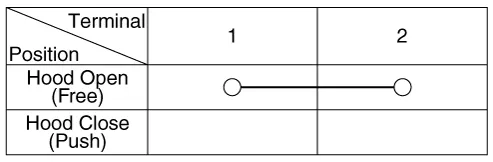
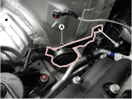
1.Disconnect the connector (A) and bolts from the hood switch.
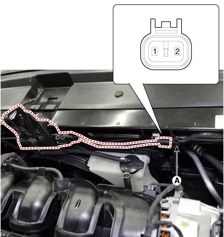
2.Check for continuity between the terminals and ground according to the table.
1.Remove the burglar horn (A) after removing a bolt and disconnecting the 2P connector from the burglar horn.
2.Test the burglar horn by connecting battery power to the terminal 1 and ground the terminal 2.
3.The burglar horn should sound. If the burglar horn fails to sound replace it.
Transmitter
1.Check that the red light flickers when the door lock or unlock button is pressed on the transmitter.
2.Remove the battery (A) and check voltage if the red light doesn't flicker.
Standard voltage : 3V
![]()
3.Insert the battery (A) into the tester (09954-2P100).
![]()
4.Push the test button and If "0.00" is displayed on screen, it means that the battery voltage is 2V or less.
5.If "L" is displayed on screen, it means that the battery is low power and it needs to replace.
6.To prevent the discharge of electricity, turn the tester power off.
7.Replace the transmitter battery with a new one, if voltage is low power then try to lock and unlock the doors with the transmitter by pressing the lock or unlock button five or six times.
8.If the doors lock and unlock, the transmitter is O.K, but if the doors don't lock and unlock, register the transmitter code, then try to lock and unlock the doors.
9.If the doors lock and unlock, the transmitter is O.K, but if the doors don't lock and unlock, replace the transmitter.
![]()
1.Connect the DLC cable of GDS to the data link connector (16 pins) in driver side crash pad lower panel, turn the power on GDS.
![]()
2.Select the vehicle model and then do "CODE SAVING"
![]()
3.After selecting "CODE SAVING" menu, button "ENTER" key, then the screen will be shown as below.
![]()
4.After removing the ignition key from key cylinder, push "ENTER" key to proceed to the next mode for code saving. Follow steps 1 to 4 and then code saving is completed.
![]()
![]()
![]()
![]()
![]()
![]()


Other information:
Hyundai Accent (HC) (2017 - 2022) Service Manual: Battery
- Specification Battery‚Ė∑ AGM60L-DINItemSpecification Capacity [20HR / 5HR] (AH)60 / 48 Cold Cranking Amperage (A)640 (SAE / EN) Reserve Capacity (Min)100 ‚ÄĘ Model type description ‚ÄĘ Cold Cranking Ampere (CCA) : Cold Cranking Amps is a rating used in the battery industry to define a battery's ability to start an engine in cold temperatures.Hyundai Accent (HC) (2017 - 2022) Service Manual: Owner maintenance
WARNING Performing maintenance work on a vehicle can be dangerous. If you lack sufficient knowledge and experience or the proper tools and equipment to do the work, have it done by an authorized HYUNDAI dealer. ALWAYS follow these precautions for performing maintenance work: Park your vehicle on level ground, move the shift lever into the P (Park, for intelligent variable transmission vehicle) position or neutral (for manual transmission vehicle), apply the parking brake, place the ignition switch in the LOCK/OFF position.
Contents
- Specifications
- Components and Components Location
- Description and Operation
- Repair procedures
- Transmitter
Categories
- Manuals Home
- Hyundai Accent Owners Manual
- Hyundai Accent Service Manual
- Questions & Answers
- Video Guides
- Useful Resources
- New on site
- Most important about car
- Privacy Policy

0.0114