Hyundai Accent (HC): Body Electrical System / Smart Key System
Contents:
- Specifications
- Components and Components Location
- Description and Operation
- Smart Key
- Smart Key Unit
- Smart Key Diagnostic
Specifications
| Items | Specification |
| Rated voltage | DC 12V |
| Operating voltage | DC 9 - 16V |
| Operating temperature | -22°F to 167°F (-30°C to 75°C) |
| Load | Max. 4mA (When welcome light function off) |
| Items | Specification |
| Frequency | 433.92 Mhz |
| Antenna type | FSK (Frequency Shift Keying) |
| Items | Specification | ||||
| Battery | Lithium battery 3V 1EA | ||||
| Distance | 30m from vehicle, RF : 30m, Passive(LF) : 0.7m | ||||
| Battery life | More than 2 years (10 times / a day)
|

Push buttons
3 (Door lock / unlock, Tailgate)
Frequency(Rx)
125 kHz
Frequency(Tx)
315 MHz
Numbers
2EA
| Items | Specification |
| Rated voltage | DC 12V |
| Operating voltage | DC 9 - 16V |
| Operating temperature | -22°F to 167°F (-30°C to 75°C) |
| Frequency | 125kHz |
| Numbers | Interior(3EA), Door(2EA), Bumper(1EA) |
Components and Components Location
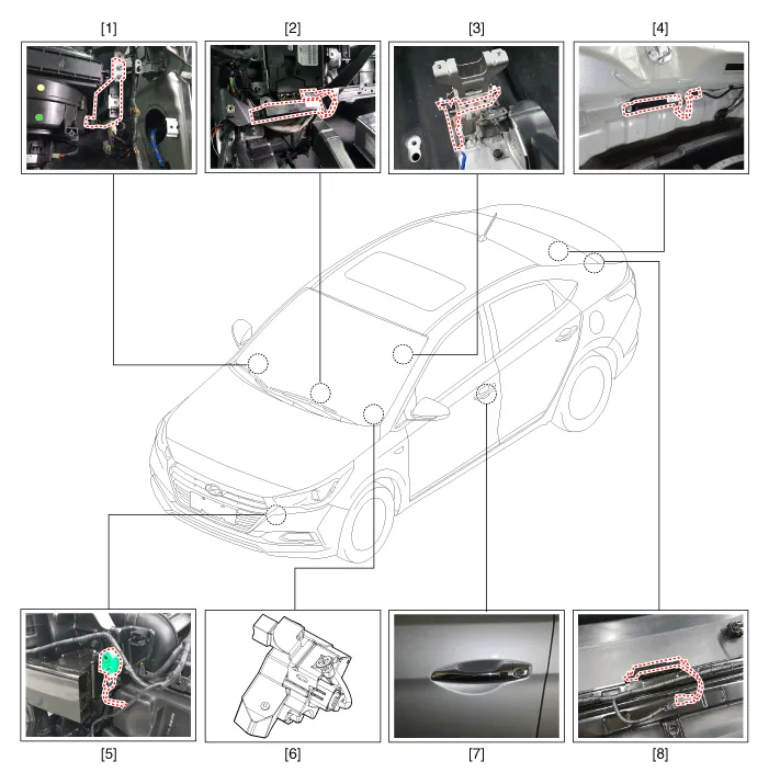
1. Smart key unit
2. Interior antenna 1
3. Interior antenna 2
4. Interior antenna 3
5. Buzzer
6. Electronic steering column lock (ESCL)
7. Door outside handle antenna
8. Bumper antenna
Description and Operation ➤
Smart Key
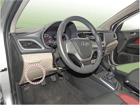
1.Connect the DLC cable of GDS to the data link connector (16 pins) in driver side crash pad lower panel, turn the power on GDS.
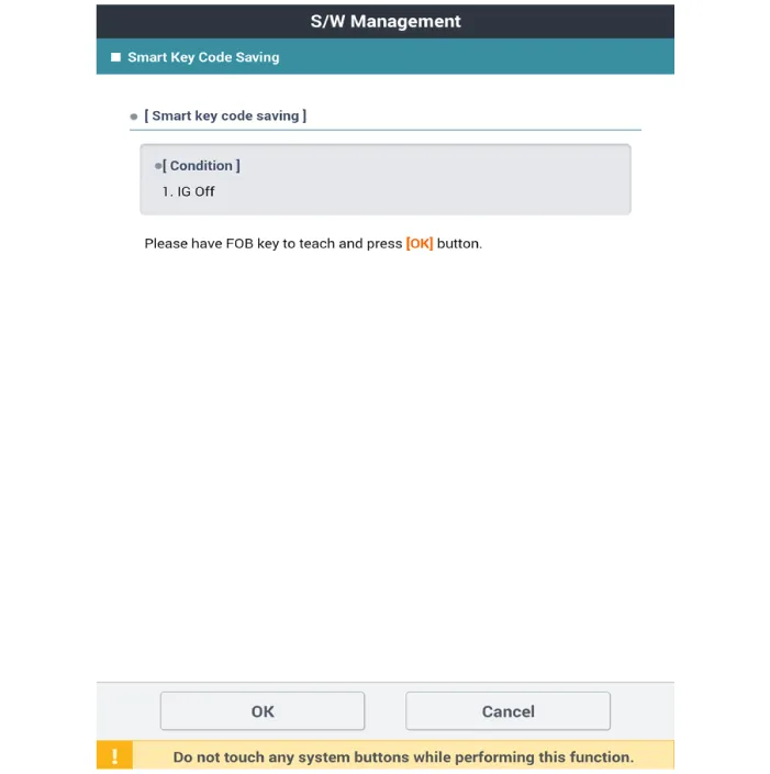
2.Select the 'S/W Management' and 'Car model'.

3.Select the 'Smart Key Unit' and 'Smart Key Code Saving'.

4.Follow the instructions on the screen.
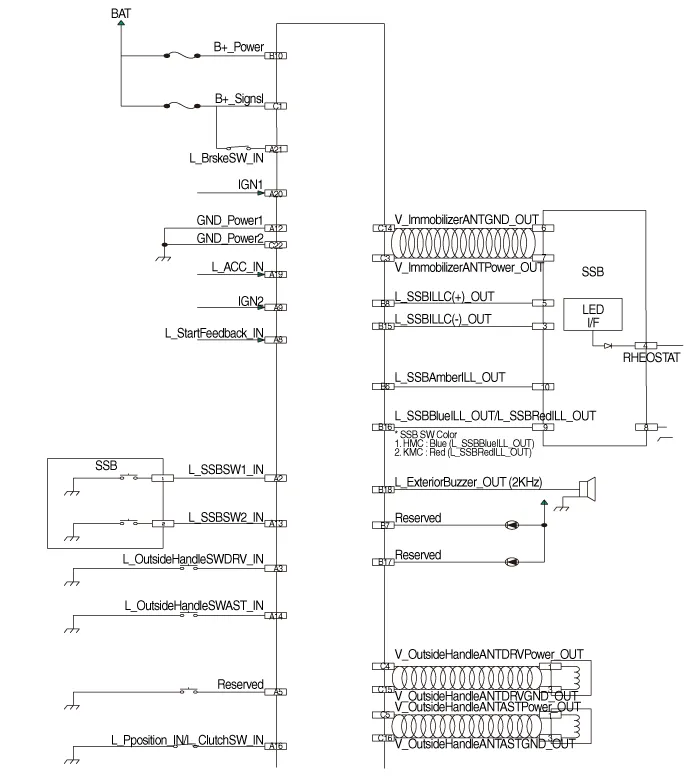
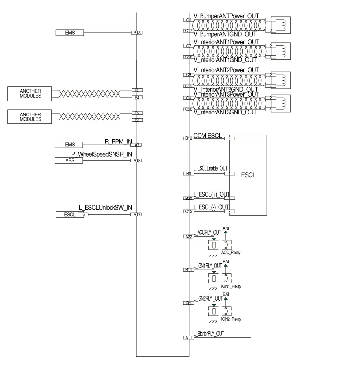
Smart Key Unit
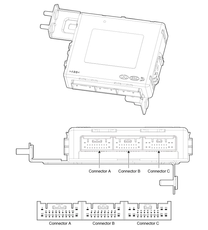
| No | Connector A | Connector B | Connector C |
| 1 | - | IGN 2 Relay output | Battery (+) |
| 2 | SSB Switch 1 input | P CAN Low | - |
| 3 | Driver outside handle switch input | P CAN High | Immobilizer antenna power output |
| 4 | - | B CAN High | Outside handle antenna driver power output |
| 5 | - | B CAN Low | Outside handle antenna assist power output |
| 6 | - | SSB Illumination (amber) output | Bumper antenna power output |
| 7 | RPM input | - | Interior antenna 1 power output |
| 8 | Start feedback input | SSB Illumination (+) output | Interior antenna 2 power output |
| 9 | IGN 2 | ESCL Enable output | Interior antenna 3 power output |
| 10 | - | Battery (+) power | - |
| 11 | Starter relay output | IGN 1 Relay output | - |
| 12 | Power1 ground | ESCL COM | - |
| 13 | SSB Switch 2 input | EMS COM | ESCL (-) Output |
| 14 | Assist outside handle switch input | - | Immobilzer antenna ground output |
| 15 | - | SSB Illumination (-)output | Outside handle antenna drvier ground output |
| 16 | P Position input / Clutch switch input | SSB Illumination (Blue) output SSB Illumination (Red) output | Outside handle antenna assist ground output |
| 17 | ESCL Unlock switch input | - | Bumper antenna ground output |
| 18 | Wheel speed sensor input | Exterior buzzer output | Interior antenna 1 groud output |
| 19 | ACC input | - | Interior antenna 2 groud output |
| 20 | IGN 2 | ESCL (+) output | Interior antenna 3 groud output |
| 21 | Brake switch input | - | |
| 22 | ACC Relay output | Ground power 2 |
1.Disconnect the negative (-) battery terminal.
2.Remove the glove box.(Refer to Body - "Glove Box Housing")
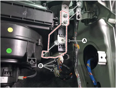
3.Remove the smart key unit (A) after loosening the nuts and disconnecting the connectors (B).
1.Disconnect the negative (-) battery terminal.
2.Remove the glove box upper cover.(Refer to Body - "Glove Box Upper Cover Assembly")
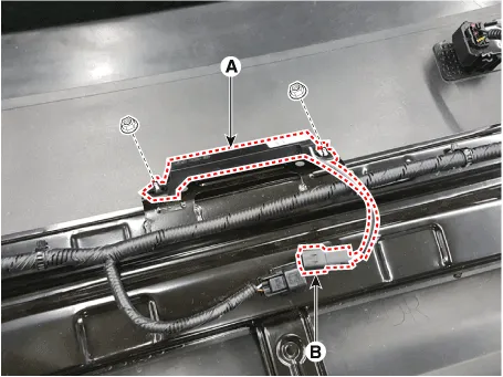
3.Remove the interior 1 antenna (A) after loosening the mounting screws (2EA) and disconnecting the connector (B).
1.Disconnect the negative (-) battery terminal.
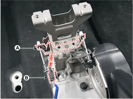
2.Remove the console rear complete assembly.(Refer to Body - "Floor Console Assembly")
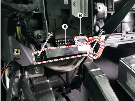
3.Remove the interior 2 antenna (A) after loosening the mounting screws (2EA) and disconnecting the connector (B).
1.Disconnect the negative (-) battery terminal.
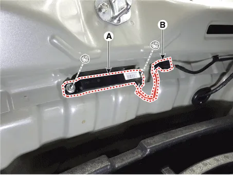
2.Remove the rear transvers trim.(Refer to Body - "Trunk Trim")
3.Remove the interior 3 antenna (A) after loosening the mounting nuts(2EA) and disconnecting the connector (B).
1.Disconnect the negative (-) battery terminal.
2.Remove the rear bumper cover.(Refer to Body - "Rear Bumper Cover")
3.Remove the exterior bumper antenna (A) after loosening the mounting nuts and disconnecting the antenna connector (B).
1.Disconnect the negative (-) battery terminal.
2.Remove the front bumper cover.(Refer to Body - "Front Bumper Cover")
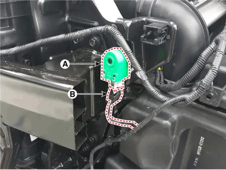
3.Remove the buzzer (A) after disconnecting the connector (B).
1.Disconnect the negative (-) battery terminal.
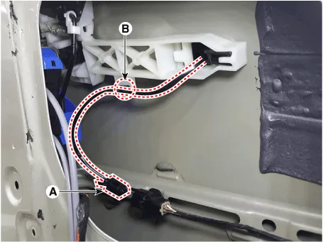
2.Remove the front door trim.(Refer to Body - "Front Door Trim")
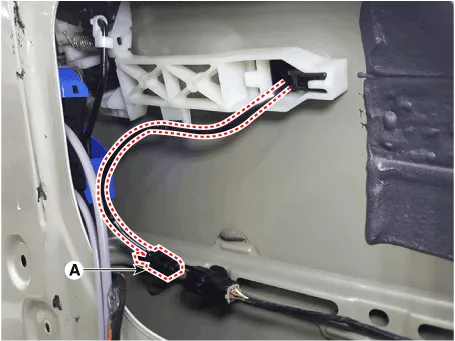
3.Disconnect the front door outside handle connector (A) and then remove the wiring mounting clip (B).
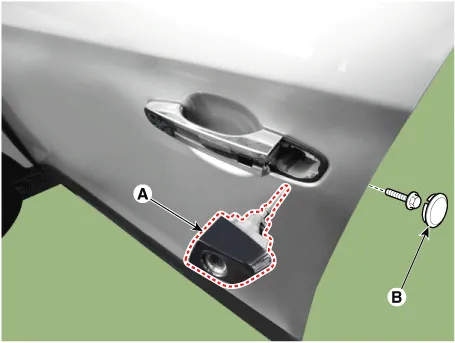
4.Remove the door outside handle cover (A) after seperating the plug hole from the door and loosening the mounting bolt.
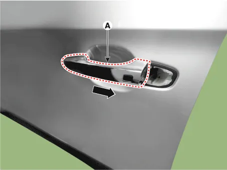
5.Remove the outside handle (A) by sliding it rearward.
1.Disconnect the front door outside handle connector (A).
2.Check for continuity between terminals No 2 and No 4.
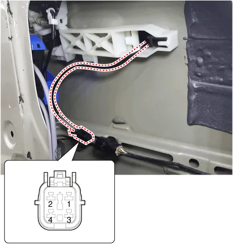
| No | Description |
| 1 | Door antenna 1 |
| 2 | Door lock/unlock button 1 |
| 3 | Door antenna 2 |
| 4 | Door lock/unlock button 2 |
1.Install the smart key unit.
2.Install the smart key unit mounting bolts and connect the connector.
3.Install the driver side crash pad lower panel.
4.Install the negative (-) battery terminal and check the smart key system.
1.Install the interior 1 antenna.
2.Install the crash pad center fascia panel.
3.Install the negative (-) battery terminal and check the smart key system.
1.Install the interior 2 antenna.
2.Install the console rear complete assembly.
3.Install the negative (-) battery terminal and check the smart key system.
1.Install the interior 3 antenna.
2.Install the rear transvers trim.
3.Install the negative (-) battery terminal and check the smart key system.
1.Install the exterior bumper antenna.
2.Install the rear bumper cover.
3.Install the negative (-) battery terminal and check the smart key system.
1.Install the buzzer.
2.Install the front left wheel guide.
3.Install the negative (-) battery terminal and check the smart key system.
1.Install the outside handle.
2.Install the door trim.
3.Install the negative (-) battery terminal and check the smart key system.
Smart Key Diagnostic
1.Problem in SMART KEY unit input.
2.Problem in SMART KEY unit.
3.Problem in SMART KEY unit output.
So the following three diagnosis operates will be the major problem solution process.1.SMART KEY unit Input problem : switch diagnosis
2.SMART KEY unit problem : communication diagnosis
3.SMART KEY unit Output problem : antenna and switch output diagnosis
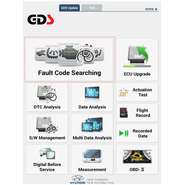
1.In the body electrical system, failure can be quickly diagnosed by using the vehicle diagnostic system (Diagnostic tool).The diagnostic system(Diagnostic tool) provides the following information.
(1)Fault Code Searching : Checking failure and code number (DTC)
(2)Data Analysis : Checking the system input/output data state
(3)Actuation test : Checking the system operation condition
(4)S/W Management : Controlling other features including system option setting and zero point adjustment
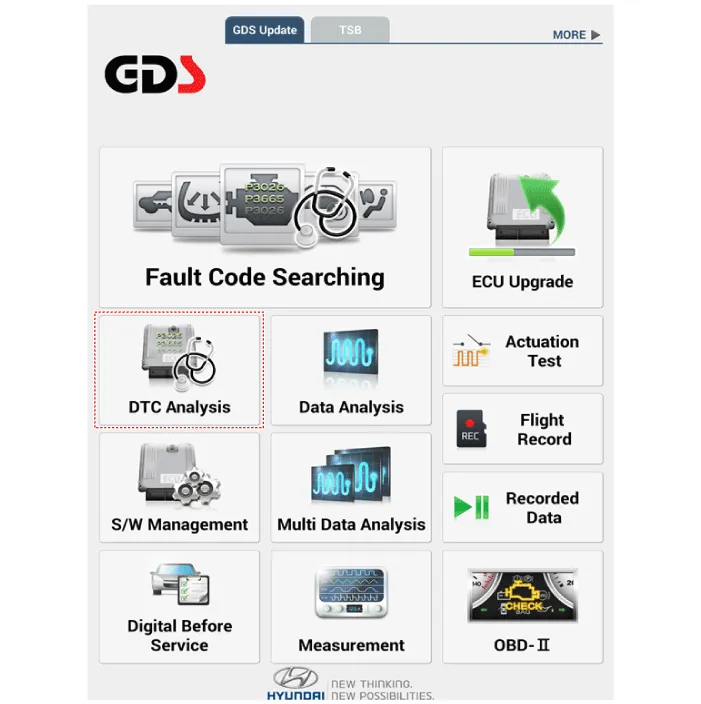
2.If diagnose the vehicle by Diagnostic tool, select "DTC Analysis" and "Vehicle".
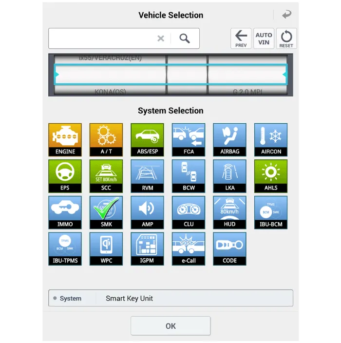
3.If check current status, select the "Data Analysis" and "Car model".

4.Select the SMK' to be checked in order to check the vehicle with the tester.
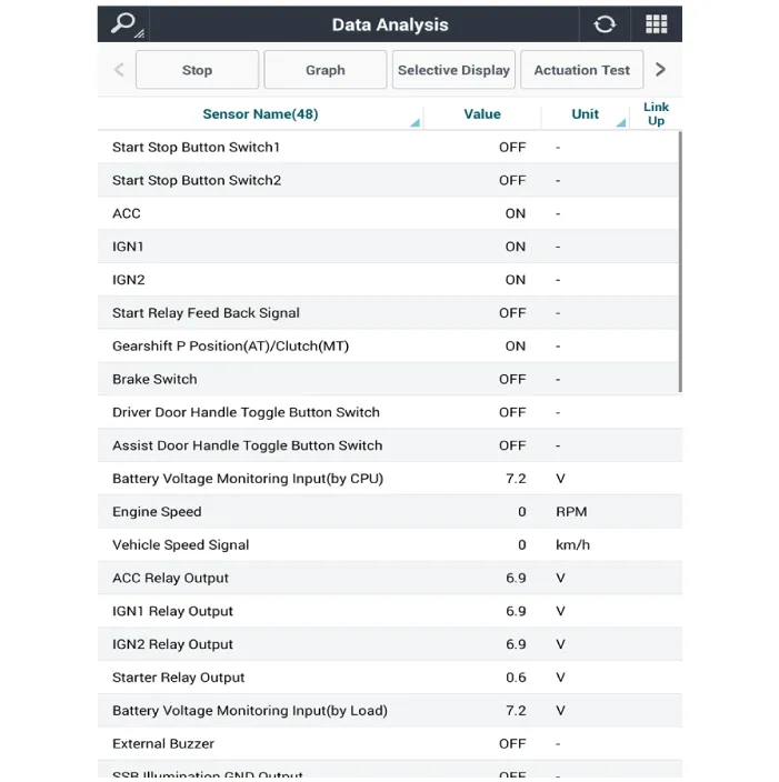
5.You can see the situation of each switch on scanner after connecting the "current data" process.
| Display | Description |
| FL Toggle SW | ON : Push button is ON in the driver door handle. |
| FR Toggle SW | ON : Push button is ON in the assist door handle. |
| Tailgate open SW | ON : Tailgate button is ON. |
| Gear P Position | ON : Shift lever is P position. |
| IGN 1 | ON : IGN switch is IG position. |
| ACC | ON : IGN switch is ACC position. |
| Brake SW | ON : Brake switch is ON. |
1.Fault code searching that the each linked components operates normal.
2.Connect the cable of Diagnostic tool to the data link connector in driver side crash pad lower panel.
3.Select the 'Fault Code Searching' and 'Car model'.
1.Connect the cable of Diagnostic tool to the data link connector in driver side crash pad lower panel.
2.Select the 'Actuation Test' and 'Car model'.
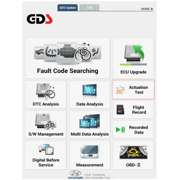
3.Set the smart key near the related antenna and operate it with a Diagnostic tool.
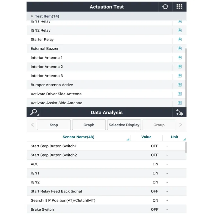
4.Set the smart key near the related antenna and operate it with a Diagnostic tool.
5.If the LED of smart key is blinking, the smart key is normal.
6.If the LED of smart key is not blinking, check the voltage of smart key battery.
7.Antenna actuation
– Interior Antenna 1
– Interior Antenna 2
– Bumper Antenna
– Driver Door Antenna
– Assist Door Antenna
1.Connect the cable of Diagnostic tool to the data link connector in driver side crash pad lower panel.
2.Select the 'S/W Management' and 'Car model'.

3.Select the 'Smart Key Unit' and 'Antenna Status Check'.

4.Set the smart key near the related antenna and operate it with a Diagnostic tool.
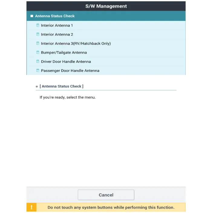
5.If the smart key runs normal , the related antenna, smart key (transmission, reception) and exterior receiver are normal.
6.Antenna status
– Interior Antenna 1
– Interior Antenna 2
– Bumper Antenna
– Driver Door Antenna
– Assist Door Antenna
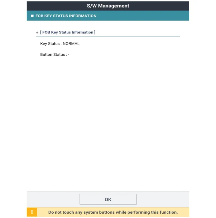
1.Connect the cable of Diagnostic tool to the data link connector in driver side crash pad lower panel.
2.Select the 'S/W Management' and 'Car model'.

3.Select the 'Smart Key Unit' and 'FOB KEY STATUS IMFORMATION'.
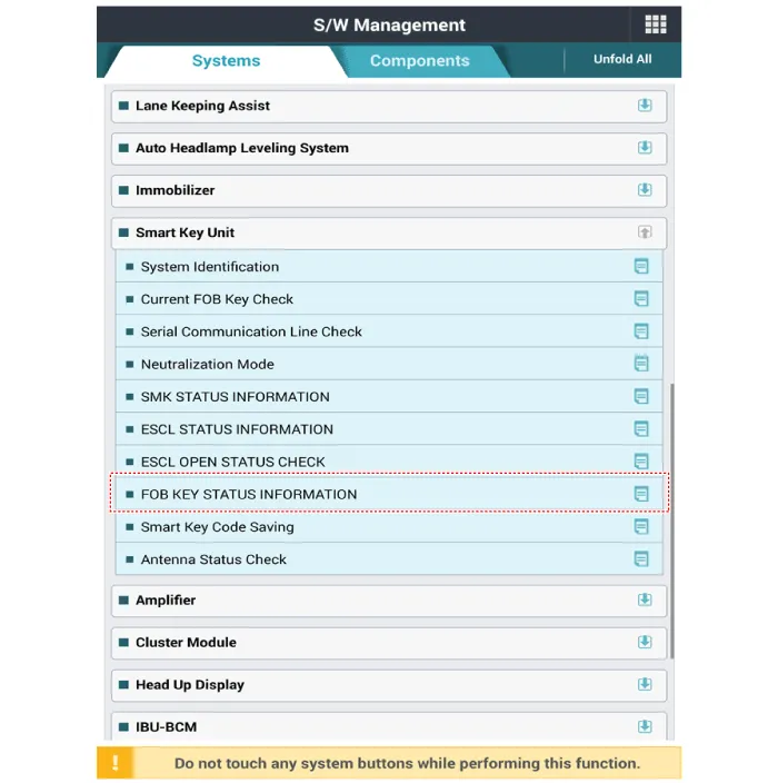
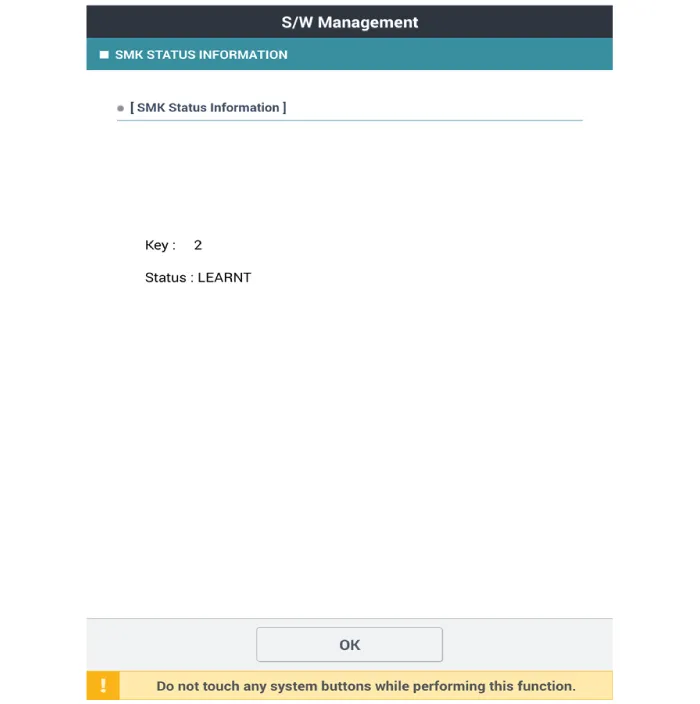
1.Connect the cable of Diagnostic tool to the data link connector in driver side crash pad lower panel.
2.Select the 'S/W Management' and 'Car model'.

3.Select the 'Smart Key Unit' and 'SMK STATUS INFORMATION'.

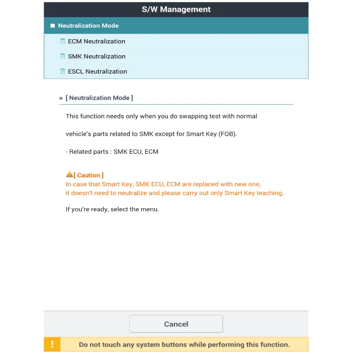
1.Connect the cable of Diagnostic tool to the data link connector in driver side crash pad lower panel.
2.Select the 'S/W Management' and 'Car model'.

3.Select the 'Smart Key Unit' and 'Neutralization Mode'.


Other information:
Hyundai Accent (HC) (2017 - 2022) Service Manual: Warning and Indicator Lights
Information Make sure that all warning lights are OFF after starting the engine. If any light remains ON, it indicates a condition that requires attention. Air Bag Warning Light This warning light illuminates: When the ignition switch is turned to the ON position. - It illuminates for approximately 6 seconds and then turns off. When there is a malfunction in the Supplemental Restraint System (SRS).Some Hyundai Accent models use a Smart Key, which you can use to lock or unlock a door (and trunk) and start the engine. For best performance, keep the Smart Key close to you and avoid storing it near strong electromagnetic sources. 1. Door Lock 2. Door Unlock 3. Trunk Unlock 4. Panic Locking To lock your Hyundai Accent using the Smart Key system: 1.
Contents
- Specifications
- Components and Components Location
- Description and Operation
- Smart Key
- Smart Key Unit
- Smart Key Diagnostic
Categories
- Manuals Home
- Hyundai Accent Owners Manual
- Hyundai Accent Service Manual
- Questions & Answers
- Video Guides
- Useful Resources
- New on site
- Most important about car
- Privacy Policy

0.01