Hyundai Accent (HC): Manual Transaxle System (M6CF1)
Hyundai Accent (HC) (2017 - 2022) Service Manual / Manual Transaxle System (M6CF1)
Contents:
- Specifications
- Special Service Tools
- Troubleshooting
- Manual Transaxle System
- Manual Transaxle Control System
Specifications
| Transaxle type | M6CF1 | |
| Engine type | Gasoline 1.6 MPI | |
| Gear ratio | 1st | 3.769 |
| 2nd | 2.045 | |
| 3rd | 1.370 | |
| 4th | 1.036 | |
| 5th | 0.794 | |
| 6th | 0.688 | |
| Reverse | 3.700 | |
| Final gear ratio | 4.267 | |
| Items | N.m | kgf.m | lb-ft |
| Oil drain plug | 58.9 - 78.5 | 6.0 - 8.0 | 43.4 - 57.8 |
| Oil filler plug | 58.9 - 78.5 | 6.0 - 8.0 | 43.4 - 57.8 |
| Shift lever assembly bolt | 8.8 - 13.7 | 0.9 - 1.4 | 9.4 - 10.1 |
| Control cable retainer | 11.8 - 14.7 | 1.2 - 1.5 | 8.7 - 10.8 |
| Back up lamp switch | 39.2 - 58.8 | 4.0 - 6.0 | 28.9 - 43.4 |
| Neutral swtich | 39.2 - 58.8 | 4.0 - 6.0 | 28.9 - 43.4 |
| Control shaft complete | 19.6 - 26.5 | 2.0 - 2.7 | 14.5 - 19.5 |
| Control cable bracket | 14.7 - 21.6 | 1.5 - 2.2 | 10.9 - 15.9 |
| Transaxle bracket mounting bolt | 88.3 - 107.9 | 9.0 - 11.0 | 65.1 - 79.8 |
| Transaxle support bracket mounting bolt | 58.9 - 78.5 | 6.0 - 8.0 | 43.4 - 57.8 |
| Roll rod bracket bolt | 49.0 - 63.7 | 5.0 - 6.5 | 36.2 - 47.0 |
| 107.9 - 127.5 | 11.0 - 13.0 | 79.6 - 94.1 | |
| Roll rod support bracket bolt | 49.0 - 68.6 | 5.0 - 7.0 | 36.2 - 50.6 |
| Start motor mounting bolt | 49.0 - 63.7 | 5.0 - 6.5 | 36.2 - 47.0 |
| Transaxle upper mounting bolt (TM=>ENG) | 42.2 - 53.9 | 4.3 - 5.5 | 31.1 - 39.8 |
| Transaxle lower mounting bolt (ENG=>TM) | 42.2 - 48.1 | 4.3 - 4.9 | 31.1 - 35.4 |
| 42.2 - 53.9 | 4.3 - 5.5 | 31.1 - 39.8 |
| Items | Recommnend lubricant | Quantity | ||||||
| Transaxle gear oil | API Service GL-4, SAE 70W • Recommended oil
| 1.5 - 1.6 L (0.40 -0.42 U.S.gal., 1.58 - 1.69 U.S.qt., 1.32- 1.40 lmp qt.) |
| Items | Specified sealant |
| Control shaft assembly | LOCTITE 5060 |
Special Service Tools
| Tool (Number and name) | Illustration | Use |
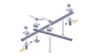
| 09200-3N000 Engine support fixture (Beam) |
| Removal and installation of the transaxle. Use this beam (SST No. : 09200-3N000) with the supporter (SST No. : 09200-2S000). ※Permit operating with 09200-38001. |
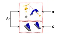
| A: 09200-2S000 B: 09200-2S100 C: 09200-2S200 Engine support fixture (Supporter) |
| Removal and installation of the transaxle. Use this beam (SST No. : 09200-38001/3N000) with the supporter (SST No. : 09200-2S000). |
| 09431-26100 Oil seal installer |
| Installation of the differential oil seal in the transaxle case and housing side. [Using with handle (SST No.09231-H1100)] |
| 09231-H1100 Bar |
| Installation of the differential oil seal in the transaxle case and housing side. [Using with oil seal installer (SST No.:09431-26100)] |


Troubleshooting
| Symptom | Suspected Area | Remedy |
| Abnormal noise | Oil level (Low) | To adding oil after inspect the parts (Oil seal, Drain plug, filler plug). |
| Oil (Wrong) | Replace the oil. | |
| Synchronizer ring (Worn or damaged) | Replace the synchronizer ring. | |
| Gear (Worn or damaged) | Replace the gear. | |
| Bearing (Worn or damaged) | Replace the bearing. | |
| Oil leak | Oil level (High) | Inspect the oil level. |
| Gasket (Damaged) | Replace the gasket. | |
| Oil seal (Worn or damaged) | Replace the oil seal. | |
| Hard shifting or impossible to shift | Oil (Wrong) | Replace the oil. |
| Clutch (Dragging) | Inspect the clutch parts (Release fork & bearing, Clutch disc) | |
| Shift fork (Worn) | Replace the shift fork. | |
| Synchronizer ring (Worn or damaged) | Replace the synchronizer ring. | |
| Gear (Worn or damaged) | Replace the gear. | |
| Hub sleeve (Worn or damaged) | Replace the hub sleeve. | |
| Jumps out of gear or shift lever moves excessively | Shift fork (Worn) | Replace the shift fork. |
| Hub sleeve (Worn or damaged) | Replace the hub sleeve. | |
| Gear (Worn or damaged) | Replace the gear. | |
| Bearing (Worn or damaged) | Replace the bearing. |
Manual Transaxle System ➤
Manual Transaxle Control System ➤


Other information:
Your Hyundai Accent electrical system is protected from electrical overload by fuses. A fuse is designed to open the circuit if current becomes excessive, helping to prevent wiring damage and protecting electrical components. This vehicle has 2 (or 3) fuse panels depending on equipment: one located in the driver’s side panel bolster and another in the engine compartment near the battery.If your vehicle is equipped with a sunroof, you can slide or tilt your sunroof with the sunroof switch located on the overhead console. In your Hyundai Accent, always make sure the opening is clear before operating the sunroof or sunshade. The sunroof can only be operated when the ignition switch is in the ON position. The sunroof can be operated for approximately 30 seconds after the ignition switch is in the ACC or LOCK position.
Contents
- Specifications
- Special Service Tools
- Troubleshooting
- Manual Transaxle System
- Manual Transaxle Control System
Categories
- Manuals Home
- Hyundai Accent Owners Manual
- Hyundai Accent Service Manual
- Questions & Answers
- Video Guides
- Useful Resources
- New on site
- Most important about car
- Privacy Policy

Copyright © 2026
0.0107
0.0107