Hyundai Accent (HC): Engine Electrical System / Starting System

Contents:

Description and Operation

- Description The starting system includes the battery, starter, solenoid switch, ignition switch, inhibitor switch (A/T), clutch pedal switch (M/T), ignition lock switch, connection wires and the battery cable.When the ignition key is turned to the start position, current flows and energizes the starter motor's solenoid coil.The solenoid plunger and clutch shift lever are activated, and the clutch pinion engages the ring gear.The contacts close and the starter motor cranks. In order to prevent damage caused by excessive rotation of the starter armature when the engine starts, the clutch pinion gear overruns.

Starter ➤

Starter Relay

- Inspection

1.Turn ignition switch OFF and disconnect the negative (-) battery terminal.

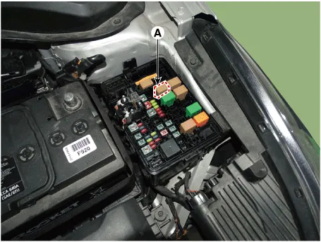
2.Remove the fuse box cover.

3.Remove the starter relay (A).

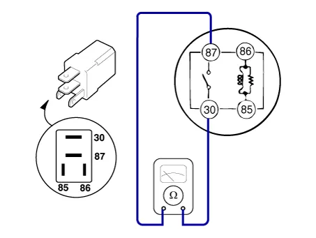
4.Check for continuity between the terminals (30 and 87) using an ohmmeter.

TerminalResistanceMeasure
30 - 871MΩ or higherIf there is continuity between the terminals, replace the relay.

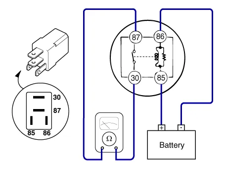
5.Apply 12V to the terminal 85 and ground to the terminal 86 and then check for continuity between the terminals (30 and 87).

TerminalResistanceMeasure
30 - 871Ω or lessIf there is no continuity between the terminals, replace the relay.

6.Install the starter relay.

7.Install the fuse box cover.

Other information:

Hyundai Accent (HC) (2017 - 2022) Service Manual: Maintenance services

You should exercise the utmost care to prevent damage to your Hyundai Accent and injury to yourself whenever performing any maintenance or inspection procedures. Use proper tools, keep the engine compartment clean, and never work near moving parts with the engine running. Have your vehicle maintained and repaired by an authorized HYUNDAI dealer. An authorized HYUNDAI dealer meets HYUNDAI's high service quality standards and receives technical support from HYUNDAI in order to provide you with a high level of service satisfaction.

Hyundai Accent (HC) (2017 - 2022) Service Manual: Front Disc Brake

- Components 1. Caliper body2. Guide rod pin3. Guide rod boot4. Caliper carrier5. Inner pad shim 6. Brake pad7. Pad retainer8. Pad return spring - Removal 1.Loosen the wheel nuts slightly.Raise the vehicle, and make sure it is securely supported. 2.Remove the front wheel and tire (A) from the front hub.Tightening torque :107.9 - 127.5 N.

Contents

Categories

 
Copyright © 2026
0.0088