Hyundai Accent: Engine Mechanical System / Timing System
Components and Components Location
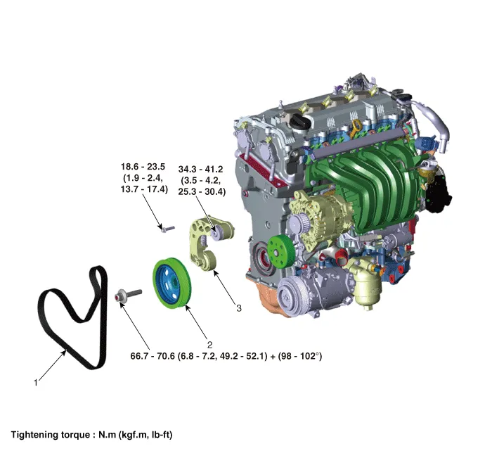
1. Drive belt
2. Crankshaft damper pulley
3. Drive belt tensioner
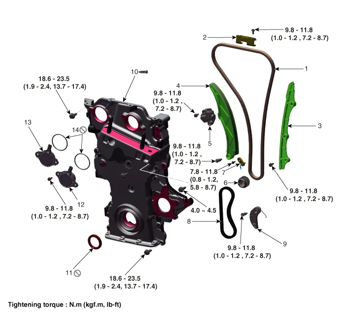
1. Timing chain
2 . Cam to cam guide
3. Timing chain guide
4. Timing chain tensioner arm
5. Timing chain tensioner
6. Crankshaft sprocket
7. Timing chain oil jet
8. Oil pump chain
9. Oil pump chain tensioner
10. Timing chain cover
11. Front oil seal
12. Intake variable force solenoid valve (VFS)
13. Exhaust variable force solenoid valves (VFS)
14. Variable force solenoid valves (VFS) O-ring
Drive Belt
1.Install the wrench to the drive belt tensioner repair hole (A) and turn it clockwise.
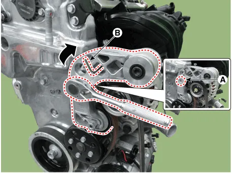

• Fix the drive belt tensioner by installing fixing pin (B) after turning the drive belt tensioner to clockwise.
• Use fixing pins that have the same outer diameter as a 6mm(0.2362 in.) hex wrench or a 6mm(0.2362 in.) hex wrench.
2.Remove the drive belt (A).
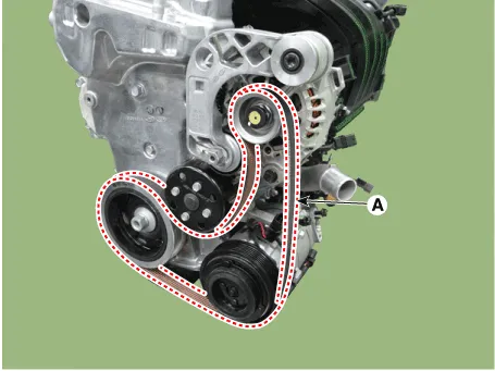

• When removing the drive belt, remove the drive belt from the water pump pulley.
3.Install in the reverse order of removal.

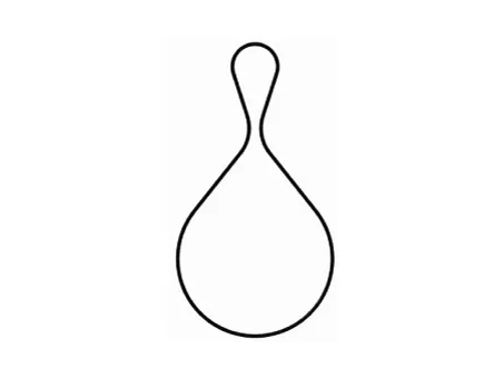
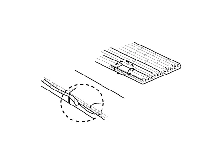
• When installation of drive belt, make the drive belt as a round hook shape bigger than alternater pulley as a picture down below. Then install it with following order of alternator → airconditioner compressor → crankshaft damper pulley → water pump → drive belt tensioner.
1.Remove the engine room under cover.(Refer to Engine and Transaxle Assembly - "Engine Room Under Cover")
2.Turn the spanner to clockwise after installing it to drive belt tensioner arm boss (A).
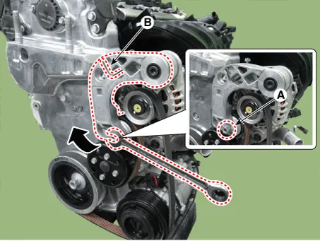

• Fix the drive belt tensioner by installing fixing pin (B) after turning the drive belt tensioner to clockwise.
• Use fixing pins that have the same outer diameter as a 6mm(0.2362 in.) hex wrench or a 6mm(0.2362 in.) hex wrench.
3.Remove the drive belt (A).
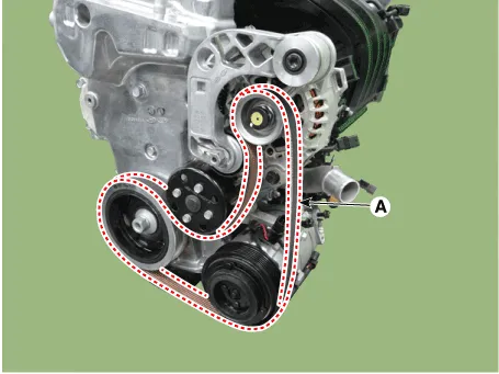

• When removing the drive belt, remove the drive belt from the water pump pulley.
4.Install in the reverse order of removal.

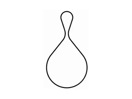
• When installation of drive belt, make the drive belt as a round hook shape bigger than alternater pulley as a picture down below. Then install it with following order of alternator → airconditioner compressor → crankshaft damper pulley → water pump → drive belt tensioner.
1.Visually check the belt for excessive wear, frayed cords etc.If any defect has been found, replace the drive belt.

• Cracks on the rib side of a belt are considered acceptable. If the belt has chunks missing from the ribs, it should be replaced.
Drive Belt Tensioner
1.Remove the drive belt.(Refer to Timing System - "Drive Belt")
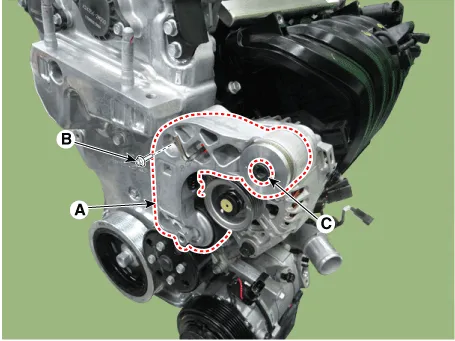
2.Remove the drive belt tensioner (A).
Tightening torque Bolt (B) : 18.6 - 23.5 N.m(1.9 - 2.4 kgf.m, 13.7 - 17.4 lb-ft)Bolt (C) : 34.3 - 41.2 N.m(3.5 - 4.2 kgf.m, 25.3 - 30.4 lb-ft)
3.Install in the reverse order of removal.
Crankshaft Damper Pulley
1.Remove the engine room under cover.(Refer to Engine and Transaxle Assembly - "Engine Room Under Cover")
2.Remove the drive belt.(Refer to Timing System - "Drive Belt")
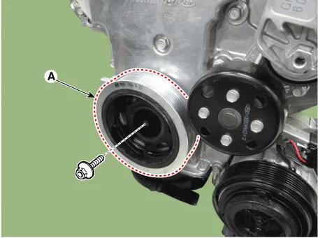
3.Remove the crankshaft damper pulley (A).
Tightening torque :66.7 - 70.6 N.m + 98 - 102°[6.8 - 7.2 kgf.m + 98 - 102°, 49.2 - 52.1 lb-ft + 98 - 102°]

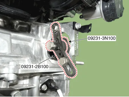
• Fix the ring gears using the SST (09231-2B100,09231-3N100) after removing the starter. Then remove the crankshaft damper pulley.
4.Install in the reverse order of removal.
Front Oil Seal
1.Remove the engine room under cover.(Refer to Engine and Transaxle Assembly - "Engine Room Under Cover")
2.Remove the drive belt.(Refer to Timing System - "Drive Belt")
3.Remove the crankshaft damper pulley.(Refer to Timing System - "Crankshaft Damper Pulley")
4.Remove the front oil seal (A).
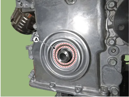
5.Using the SST (0K231-2C200), install a new front oil seal.
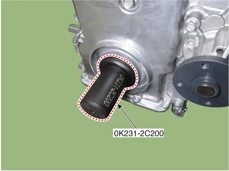

• Always use a new front oil seal.
6.Install in the reverse order of removal.
Timing Chain Cover ➤
Timing Chain ➤
Other information:
Hyundai Accent (HC) (2017 - 2022) Service Manual: Front Disc Brake
- Components 1. Caliper body2. Guide rod pin3. Guide rod boot4. Caliper carrier5. Inner pad shim 6. Brake pad7. Pad retainer8. Pad return spring - Removal 1.Loosen the wheel nuts slightly.Raise the vehicle, and make sure it is securely supported. 2.Remove the front wheel and tire (A) from the front hub.Tightening torque :107.9 - 127.5 N.Hyundai Accent (HC) (2017 - 2022) Service Manual: Schematic Diagrams
- Schematic Diagrams - Termianal function Wire NoDesignationCurrent maxmin 13Ground for recirculation pump39A10A 1Voltage supply for pump motor39A10A 25Voltage supply for solenoid valves15A2A 38Ground for solenoid valves and ECU15A2A 22Signal wheel speed sensor FL16.8 mA5.9 mA 33Voltage supply for the active wheel speed sensor RL16.
Contents
- Components and Components Location
- Drive Belt
- Drive Belt Tensioner
- Crankshaft Damper Pulley
- Front Oil Seal
- Timing Chain Cover
- Timing Chain
Categories
- Manuals Home
- Hyundai Accent Owners Manual
- Hyundai Accent Service Manual
- New on site
- Most important about car


