Hyundai Accent (HC): ESP(Electronic Stability Program) System / Description and Operation
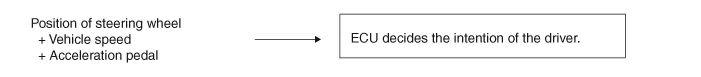
1.STEP 1The ESP analyzes the intention of the driver.
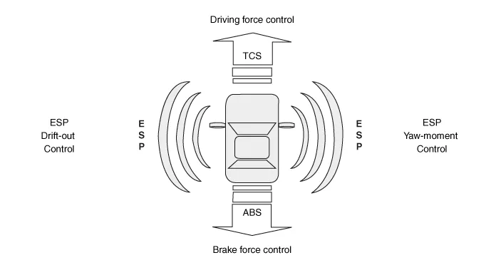
2.STEP 2It analyzes the movement of the ESP vehicle.
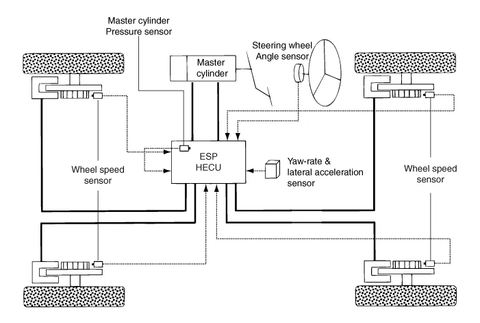
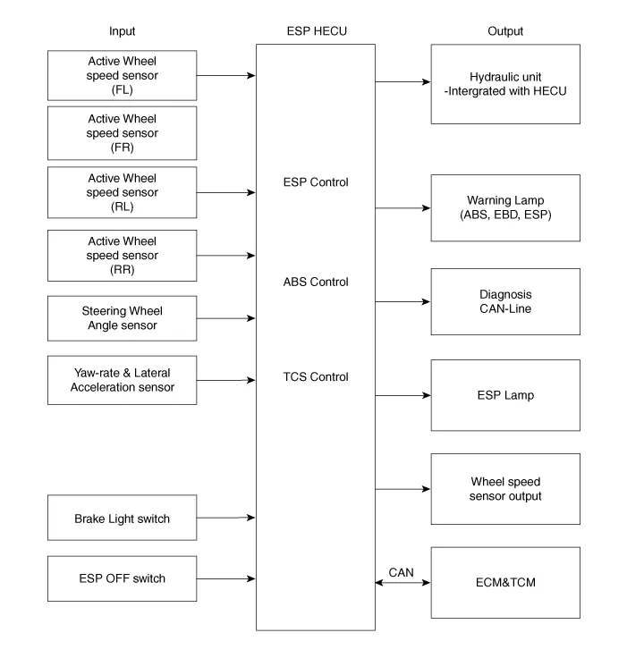
3.STEP 3The HECU calculates the required strategy, then actuates the appropriate valves and sents torque control requests via CAN to maintain vehicle stability.
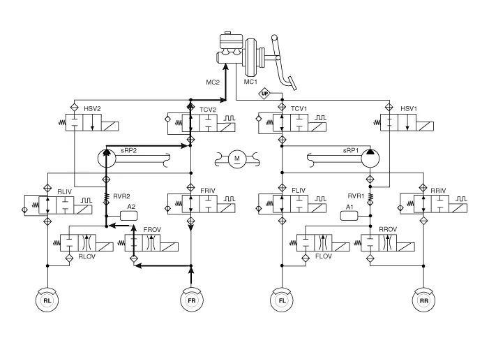
1.ESP Non-operation-Normal braking.
| Inlet valve (IV) | Outlet valve (OV) | Traction Control Valve (TCV) | High pressure switch valve (HSV) | Return pump | |
| Normal braking | Open | Close | Open | Close | OFF |
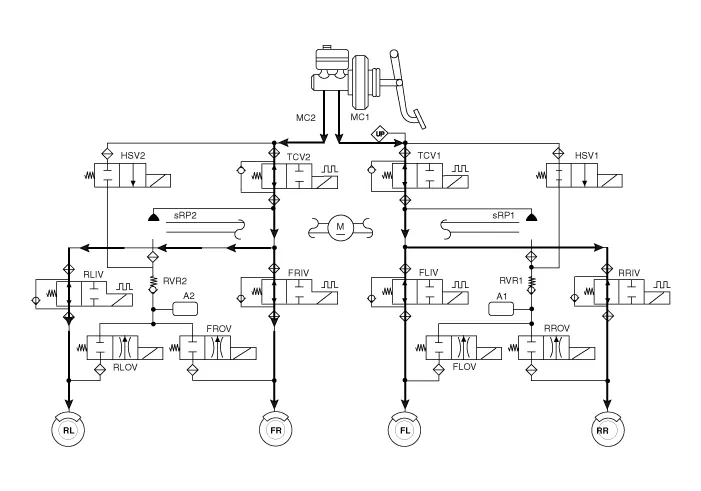

• IV : Inlet Valve
• OV : Outlet Valve
• RL : Rear left wheel
• FR : Front right wheel
• FL : Front left wheel
• RR : Rear right wheel
• RP : Return pump
• TCV : Traction Control Valve
• HSV : High pressure Switch Valve
2.ESP Increase Mode
| Inlet valve (IV) | Outlet valve (OV) | Traction Control Valve (TCV) | High pressure switch valve (HSV) | Return pump | |
| Normal braking | Open | Close | Close (Partial) | Open | ON (Motor speed control) |
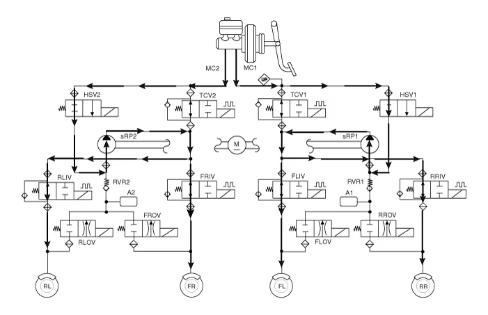

• IV : Inlet Valve
• OV : Outlet Valve
• RL : Rear left wheel
• FR : Front right wheel
• FL : Front left wheel
• RR : Rear right wheel
• RP : Return pump
• TCV : Traction Control Valve
• HSV : High pressure Switch Valve
3.ESP Hold Mode (FR is only controlled.)
| Inlet valve (IV) | Outlet valve (OV) | Traction Control Valve (TCV) | High pressure switch valve (HSV) | Return pump | |
| Normal braking | Close | Close | Close (Partial) | Open | OFF |
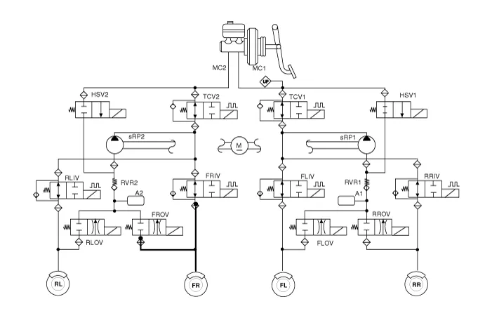

• IV : Inlet Valve
• OV : Outlet Valve
• RL : Rear left wheel
• FR : Front right wheel
• FL : Front left wheel
• RR : Rear right wheel
• RP : Return pump
• TCV : Traction Control Valve
• HSV : High pressure Switch Valve
4.ESP Decrease Mode (FR is only controlled)
| Inlet valve (IV) | Outlet valve (OV) | Traction Control Valve (TCV) | High pressure switch valve (HSV) | Return pump | |
| Normal braking | Close | Open | Close (Partial) | Open | ON (Motor speed low control) |

• IV : Inlet Valve
• OV : Outlet Valve
• RL : Rear left wheel
• FR : Front right wheel
• FL : Front left wheel
• RR : Rear right wheel
• RP : Return pump
• TCV : Traction Control Valve
• HSV : High pressure Switch Valve
– During the initialization phase after IGN ON. (continuously 3 seconds).
– In the event of inhibition of ESP functions by failure.
– During diagnostic mode.
– When the ECU Connector is separated from ECU.
– During the initialization phase after IGN ON. (continuously 3 seconds).
– When the Parking Brake Switch is ON or brake fluid level is low.
– When the EBD function is out of order .
– During diagnostic mode.
– When the ECU Connector is separated from ECU.
– During the initialization phase after IGN ON. (continuously 3 seconds).
– In the event of inhibition of ESP functions by failure.
– During dignostic mode.
– When the ESP control is operating. (Blinking - 2Hz)
– During the initialization phase after IGN ON. (continuously 3 seconds).
– When driver turn off the ESP function by on/off switch.


Other information:
Hyundai Accent (HC) (2017 - 2022) Service Manual: Heater & A/C Control Unit (FATC)
- Components ConnectorPin NOFunctionConnectorPin NOFunction A1Battery (+)A21IGN2 2ADS Sensor (PWM)22IGN1 3ILL+ (TAIL)23HTD (Rear defog indicator) 4C_CAN High24PAB off signal 5C_CAN Low25PAB IGN1 6Defrost actuator (Open)26Sensor ground REF (+5V) 7Defrost actuator (Close)27Detent out (-) 8Mode control actuator (Vent)28Ambient Temperature Sensor (+) 9Mode control actuator (Def)29Evaporator Temperature Sensor (+) 10Temperature control actuator (Cool)30Photo sensor (-) 11Temperature control actuator (Warm)31- 12Intake actuator (Fresh)32- 13Intake actuator (Recirculation)33Hazard signal 14Mode control actuator (Feedback)34Rear defog swich 15Tmperature control actuator (Feedback)35- 16Intake actuator (Feedback)36Blower motor (+) 17Defrost actuator (Feedback)37Fet (Drain feedback) 18ECV+38Fet (Gate) 19ECV- (Ground)39Sensor ground 20ILL- (RHEO)40Ground - Self Diagnosis 1.Hyundai Accent (HC) (2017 - 2022) Service Manual: Ignition Lock Switch
- Specifications ItemSpecifications Working voltageDC 12.5V ± 0.3V Operating forceInitial position : 0.25 ± 0.15N(0.025 ± 0.015kg, 0.056 ± 0.034lb) Full position : 0.8 ± 0.2 N(0.08 ± 0.02 kgf, 0.579 ± 0.014 lb-ft) Working temperature-40℃ ~ 80℃ (-40℉ ~ 176℉) - Description – Ignition lock switch is mounted on the clutch pedal.
Categories
- Manuals Home
- Hyundai Accent Owners Manual
- Hyundai Accent Service Manual
- Questions & Answers
- Video Guides
- Useful Resources
- New on site
- Most important about car
- Privacy Policy

0.0057