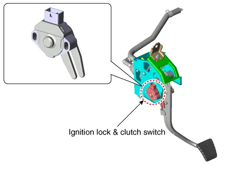
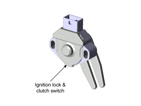
Hyundai Accent (HC): Clutch System / Clutch Switch
| Item | Specifications |
| Working voltage | DC 12.5V ± 0.3V |
| Operating force | Initial position : 0.25 ± 0.15N(0.025 ± 0.015kg, 0.056 ± 0.034lb) |
| Full position : 0.8 ± 0.2 N(0.08 ± 0.02 kgf, 0.579 ± 0.014 lb-ft) | |
| Working temperature | -40℃ ~ 80℃ (-40℉ ~ 176℉) |
– Clutch operation is detected through clutch switch signal. This signal enables ECM to cope with instant change of load condition.
– Clutch switch signal is used to detect engaged gear with vehicle speed and engine speed.
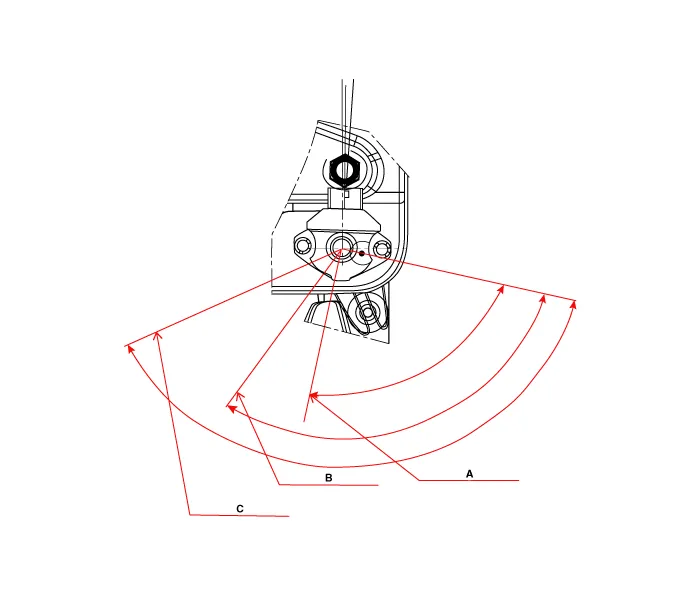
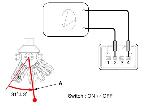
Ignition lock & clutch switch operating locus
– If the clutch pedal is pressed down, (A) operate ignition lock switch at a location.
| Engine | Operation switch stroke | ||
| Gasoline 1.6 | Clutch switch ON -> OFF (A) | Ignition lock switch OFF -> ON (B) | Switch full stroke (C) |
| 87.5˚ ± 3˚ | 110˚ ± 5.5˚ | 117.3˚ | |
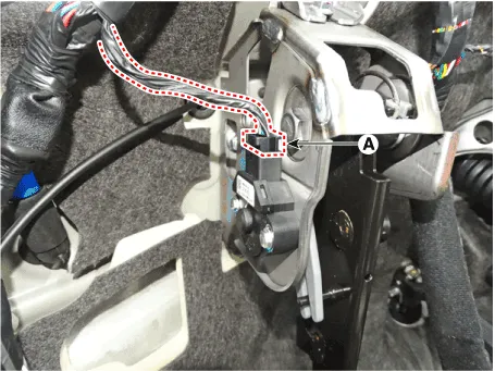
1.Turn ignition switch OFF and disconnect the negative (-) battery cable.
2.Disconnect the ignition lock & clutch switch connector (A).
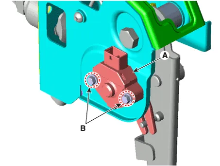
3.Remove the ignition lock & clutch switch (A) after loosening the bolts (B).
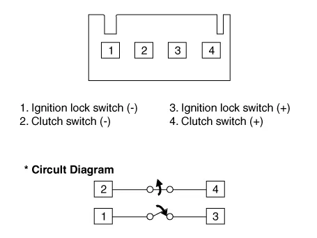
Component Inspection
1.Turn ignition switch OFF and disconnect the negative (-) battery cable.
2.Remove the ignition lock & clutch switch.
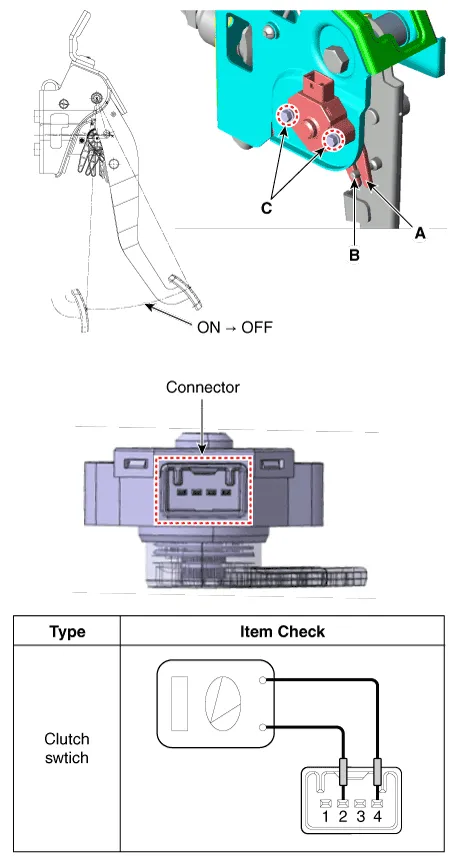
3.Rotate the switch lever to the direction of the arrow to check the operating point (A).
1.Install is proceeds as follows.※ How to install the ignition lock & clutch switch(A) After inserting the switch lever (A) into the clutch pedal pin (B), pre-tighten the switch mounting bolts (C).(B) Set the clutch switches so as to confirm that the electric current is applied to the pins ② and ④.(C) Fix the clutch pedal to the ignition lock switch ON→OFF strokes (F).(D) With the pedal fixed, rotate the switch clockwise and counter-clockwise to set it to a position at the transition from ON to OFF. Then, tighten the mounting bolts (C) to the specified torque.(E) Once completing the assembly, check again that the switch is correctly operating.※ ON→OFF stroke tolerance should be within ± 3 mm (0.1181 in.)
ON → OFF Position (F) : 70 ± 3 mm (2.7559 ± 0.1181 in.)Tightening torque :2.0 - 3.9 N.m (0.2 - 0.4 kgf.m, 1.4 - 2.9 lb-ft)


Other information:
Hyundai Accent (HC) (2017 - 2022) Service Manual: Power Window Switch
- Circuit Diagram Power Window Main Swtich Front+Rear, Door Lock + Drive Safety Front+Rear, Door Lock, Auto Down Front Only, Door Lock, Auto Dwon Front+Rear, Auto Down Front Only, Auto Dwon Assist Power Window Switch (Manual) Rear Power Window Switch (Manual) - Inspection Power Window Main Switch Inspection 1.Hyundai Accent (HC) (2017 - 2022) Service Manual: Repair procedures
- Replacement [Removal] • Put on gloves to prevent hand injuries. • Use seat covers to avoid damaging any surfaces. 1.Remove the roof garnish.(Refer to Body Side Molding - "Roof Garnish") 2.Remove the front pillar trim.(Rear to Interior Trim - "Front Pillar Trim") 3.Remove the inside rear view mirror assembly.
Categories
- Manuals Home
- Hyundai Accent Owners Manual
- Hyundai Accent Service Manual
- Questions & Answers
- Video Guides
- Useful Resources
- New on site
- Most important about car
- Privacy Policy

0.0053