Hyundai Accent (HC): Brake System (ABS/ESC) / ABS(Anti-Lock Brake System)
Contents:
- Description and Operation
- Components and Components Location
- Schematic Diagrams
- Repair procedures
- Troubleshooting
- ABS Control Module
- Front Wheel Speed Sensor
- Rear Wheel Speed Sensor
Description and Operation
– Input of signal from the wheel speed sensors attached to each wheel.
– Control of braking force.
– Failsafe function.
– Self diagnosis function.
– Interface with the external diagnosis tester.
– Brake tube length from Master cylinder port to HECU inlet port should be max. 1m
– The position should not be close to the engine block and not lower than the wheel.
– OvervoltageWhen overvoltage is detected(above 16.8 V), the ECU switches off the valve relay and shuts down the system.When voltage is returned to operating range, the system goes back to the normal condition after the initialization phase.
– UndervoltageIn the event of undervoltage(below 9.3 V), ABS control shall be inhibited and the warning lamp shall be turned on.When voltage is returned to operating range, the warning lamp is switched off and ECU returns to normal operating mode.
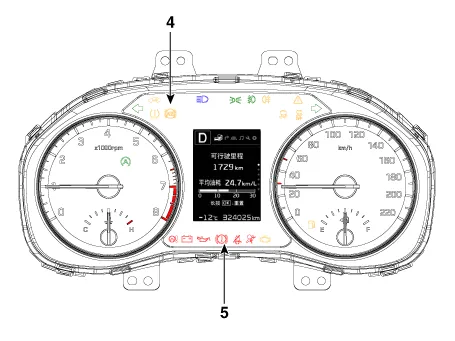
1.ABS Warning LampThe active ABS warning lamp indicates the selftest and failure status of the ABS. The ABS warning lamp shall be on :
– During the initialization phase after IGN ON. (continuously 3 seconds).
– In the event of inhibition of ABS functions by failure.
– During diagnostic mode.
– When the ECU Connector is separated from ECU.
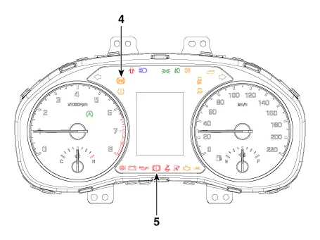
2.EBD/Parking brake Warning LampThe active EBD warning lamp indicates the selftest and failure status of the EBD. However, in case the Parking Brake Switch is turned on, the EBD warning lamp is always turned on regardless of EBD functions.The EBD warning lamp shall be on:
– During the initialization phase after IGN ON. (continuously 3 seconds).
– When the Parking Brake Switch is ON or brake fluid level is low.
– When the EBD function is out of order.
– During diagnostic mode.
– When the ECU Connector is separated from ECU.
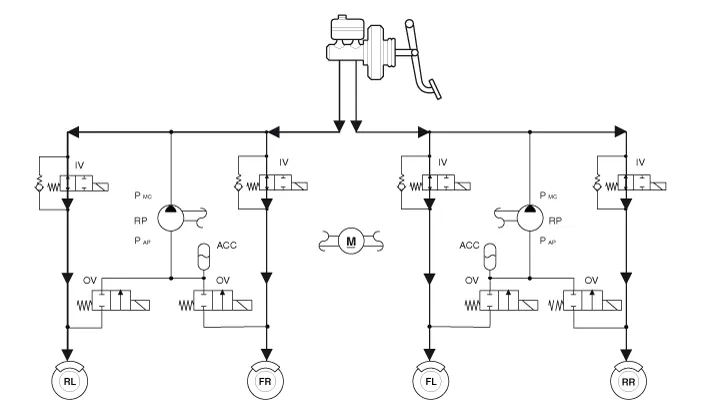
1.Normal Braking without ABS
| Inlet valve (IV) | Outlet valve (OV) | Return pump | |
| Operation | Open | Close | OFF |


• IV : Inlet Valve
• OV : Outlet Valve
• RL : Rear left wheel
• FR : Front right wheel
• FL : Front left wheel
• RR : Rear right wheel
• RP : Return pump
2.Decrease Mode
| Inlet valve (IV) | Outlet valve (OV) | Return pump | |
| Operation | Close | Open | ON (Motor speed control) |
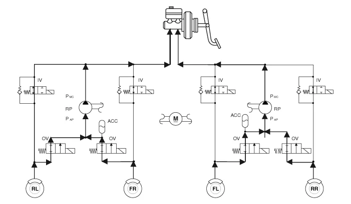

• IV : Inlet Valve
• OV : Outlet Valve
• RL : Rear left wheel
• FR : Front right wheel
• FL : Front left wheel
• RR : Rear right wheel
• RP : Return pump
3.Hold Mode
| Inlet valve (IV) | Outlet valve (OV) | Return pump | |
| Operation | Close | Close | ON (Motor speed control) |
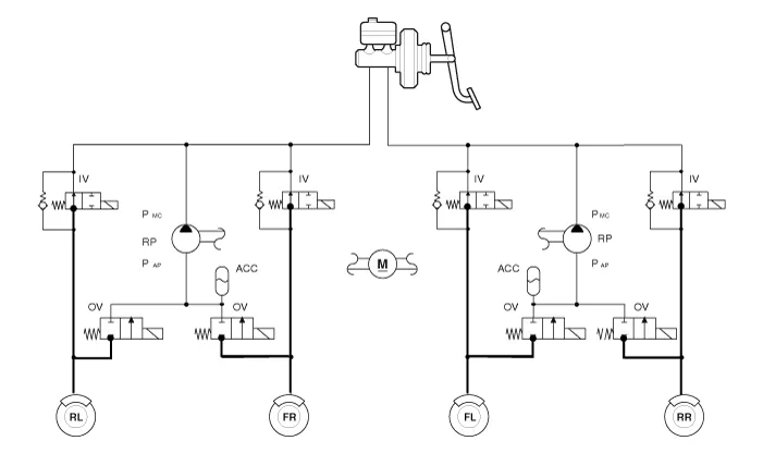

• IV : Inlet Valve
• OV : Outlet Valve
• RL : Rear left wheel
• FR : Front right wheel
• FL : Front left wheel
• RR : Rear right wheel
• RP : Return pump
4.Increase Mode
| Inlet valve (IV) | Outlet valve (OV) | Return pump | |
| Operation | Open | Close | ON (Motor speed control) |

• IV : Inlet Valve
• OV : Outlet Valve
• RL : Rear left wheel
• FR : Front right wheel
• FL : Front left wheel
• RR : Rear right wheel
• RP : Return pump
Components and Components Location

1. ABS Control Module (HECU)
2. Front Wheel Speed Sensor
3. Rear Wheel Speed Sensor
4. ABS Warning lamp
5. EBD / Parking brake warning lamp
Schematic Diagrams
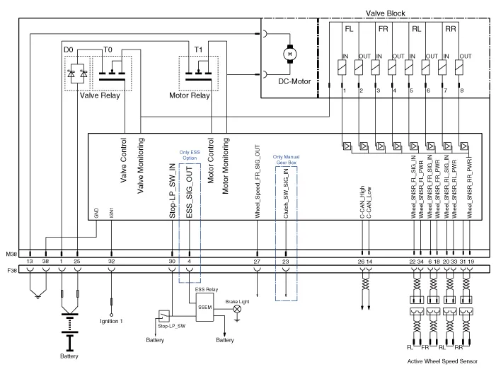

| Wire No | Designation | Current | |
| max | min | ||
| 13 | Ground for recirculation pump | 39A | 10A |
| 1 | Voltage supply for pump motor | 39A | 10A |
| 25 | Voltage supply for solenoid valves | 15A | 2A |
| 38 | Ground for solenoid valves and ECU | 15A | 2A |
| 22 | Signal wheel speed sensor FL | 16.8 mA | 5.9 mA |
| 33 | Voltage supply for the active wheel speed sensor RL | 16.8 mA | 5.9 mA |
| 19 | Voltage supply for the active wheel speed sensor RR | 16.8 mA | 5.9 mA |
| 18 | Voltage supply for the active wheel speed sensor FR | 16.8 mA | 5.9 mA |
| 6 | Signal wheel speed sensor FR | 16.8 mA | 5.9 mA |
| 14 | CAN LOW | 30 mA | 20 mA |
| 34 | Voltage supply for the active wheel speed sensor FL | 16.8 mA | 5.9 mA |
| 20 | Signal wheel speed sensor RL | 16.8 mA | 5.9 mA |
| 32 | Voltage for HECU | 1A | 500 mA |
| 31 | Signal wheel speed sensor RR | 16.8 mA | 5.9 mA |
| 30 | Brake light switch | 10 mA | 5 mA |
| 26 | CAN HIGH | 30 mA | 20 mA |
| 27 | Wheel speed sensor output | Open Draim | |
Repair procedures
1.Remove the reservoir cap and fill the brake reservoir with brake fluid.

• If there is any brake fluid on any painted surface, wash it off immediately.
• When pressure bleeding, do not depress the brake pedal.
• Recommended fluid........ DOT3 or DOT4
2.Connect a clear plastic tube to the wheel cylinder bleeder plug and insert the other end of the tube into a half filled clear plastic bottle.
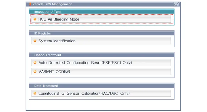
3.Connect the GDS to the data link connector located underneath the dash panel.
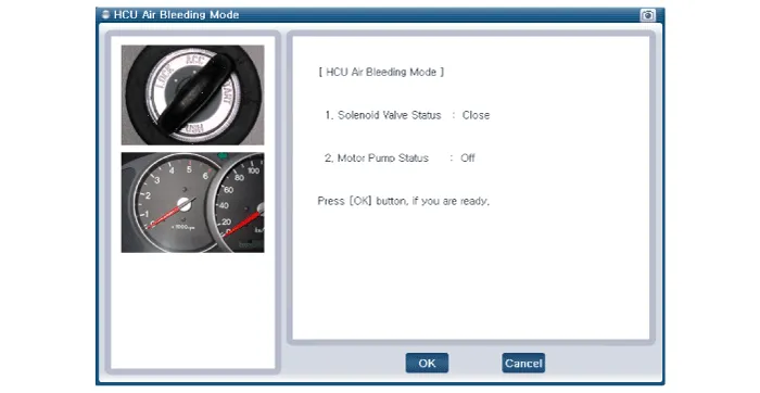
4.Select and operate according to the instructions on the GDS screen

• You must obey the maximum operating time of the ESC motor with the GDS to prevent the motor pump from burning.
1)Select vehicle name.
2) Select ABS/ESC system.
3)Select HCU air bleeding mode.
5.Pump the brake pedal several times, and then loosen the bleeder
screw until fluid starts to run out without bubbles. Then close the
bleeder screw (A).
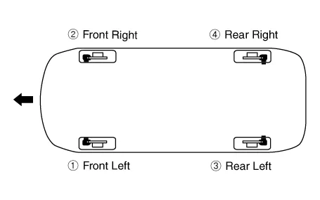
6.Repeat the procedure for wheel in the sequence shown below until air bubbles no longer appear in the fluid.
7.Refill the master cylinder reservoir to MAX (upper) level line.
Troubleshooting ➤
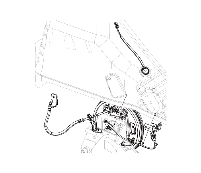
ABS Control Module
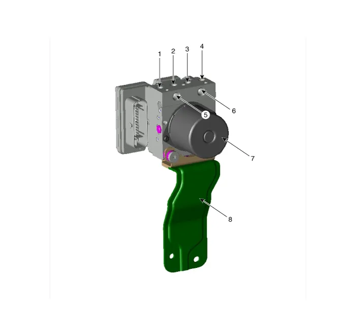
1. Front - right tube
2. Rear - left tube
3. Rear - right tube
4. Front - left tube
5. MC SEC
6. MC PRI
7. ABS control module (HECU)
8. Bracket
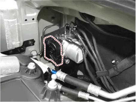
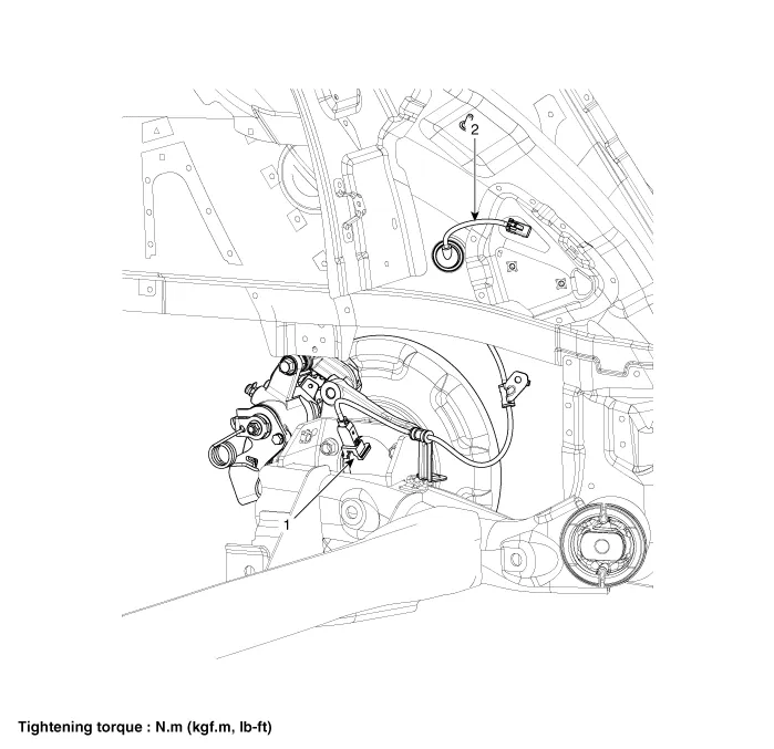
1.Turn the ignition switch OFF and then disconnect the negative (-) battery cable.
2.Pull up the lock of the HECU connector, then disconnect the connector.
3.Remove the brake fluid from the master cylinder reservoir with a syringe.

• Be sure to completely remove foreign substances from around brake fluid reservoir and cap before opening the reservoir cap. If not, it may cause contamination of brake fluid and deterioration in braking performance.
• Do not spill brake fluid on the vehicle, it may damage the paint; if brake fluid does contact the paint, wash it off immediately with water.
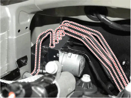
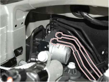
4.Disconnect the brake tubes from the HECU by unlocking the nuts counterclockwise with a spanner.
Tightening torque : 13.7 - 16.7 N.m (1.4 - 1.7 kgf.m, 10.1 - 12.3 lb-ft)
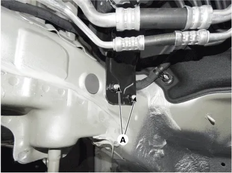
5.Loosen the HECU bracket bolts (A), then remove HECU and bracket.
Tightening torque :16.7 - 25.5 N.m (1.7 - 2.6 kgf.m, 12.3 - 18.8 lb-ft)
6.Remove the 3 bolts, then remove the bracket from HECU.
Tightening torque :7.8 - 9.8 N.m (0.8 - 1.0 kgf.m, 5.8 - 7.2 lb-ft)
1.To install, reverse the removal procedure.
2.Tighten the HECU mounting bolts and nuts to the specified torque.
3.After installation, bleed the brake system. (Refer to ABS System - "ABS System Bleeding")
Front Wheel Speed Sensor
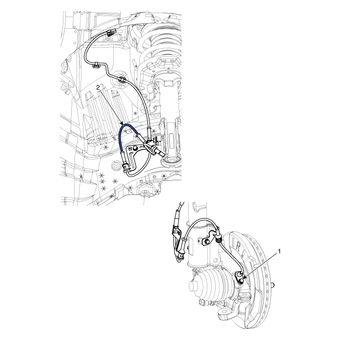
1. Front wheel speed sensor
2. Front wheel speed sensor cable
1.Loosen the wheel nuts slightly.Raise the vehicle, and make sure it is securely supported.
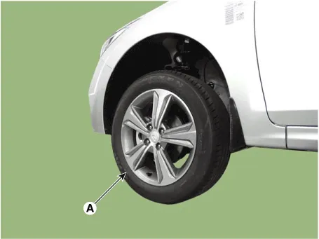
2.Remove the front wheel and tire (A) from the front hub.
Tightening torque :107.9 - 127.5 N.m (11.0 - 13.0 kgf.m, 79.6 - 94.0 lb-ft)

• Be careful not to damage the hub bolts when removing the front wheel and tire.
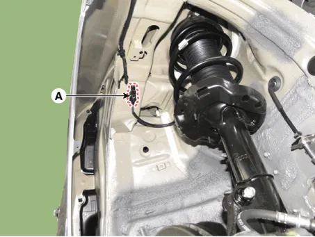
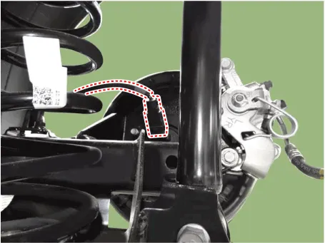
3.Loosen the mounting holt and then remove the wheel speed sensor cable from the strut assembly.
Tightening torque :7.8 - 11.8 N.m (0.8 - 1.2 kgf.m, 5.8 - 8.7 lb-ft)
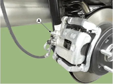
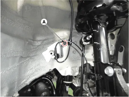
4.Remove the wheel speed sensor cable braket bolt (A).
Tightening torque : 7.8 - 11.8 N.m (0.8 - 1.2 kgf.m, 5.8 - 8.7 lb-ft)
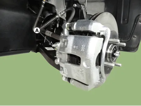
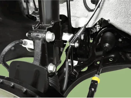
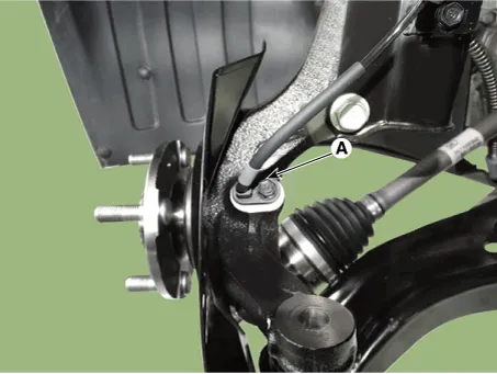
5.Loosen the bolt and then remove the wheel speed sensor (A).
Tightening torque :7.8 - 11.8 N.m (0.8 - 1.2 kgf.m, 5.8 - 8.7 lb-ft)
6.Remove the front wheel guard.(Refer to Body - "Front Wheel Guard")
7.Disconnect the wheel speed sensor connector (A) and then remove it.
8.To install, reverse the removal procedure.
1.Measure the output voltage between the terminal of the wheel speed sensor and the body ground.

• In order to protect the wheel speed sensor, when measuring output voltage, a 100Ω resister must be used as shown.
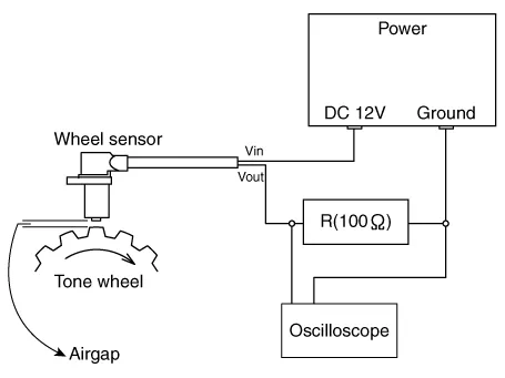
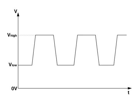
2.Compare the change of the output voltage of the wheel speed sensor to the normal change of the output voltage as shown below.

V_low : 0.59V - 0.84VV_high : 1.18V - 1.68VFrequency range : 1 - 2,500 Hz
Rear Wheel Speed Sensor
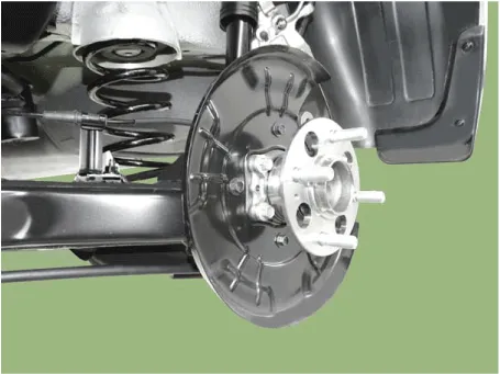
[Drum Type]
1. Front wheel speed sensor
2. Front wheel speed sensor cable
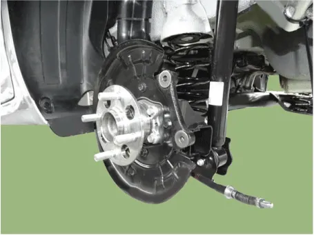
[Disc Type]
1. Front wheel speed sensor
2. Front wheel speed sensor cable
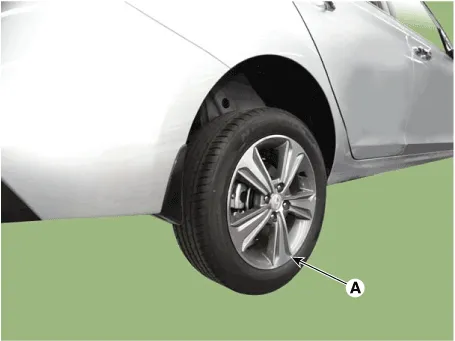
1.Loosen the wheel nuts slightly.Raise the vehicle, and make sure it is securely supported.
2.Remove the rear wheel and tire (A) from front hub.
Tightening torque :107.9 - 127.5 N.m (11.0 - 13.0 kgf.m, 79.6 - 94.0 lb-ft)


• Be careful not to damage the hub bolts when removing the rear wheel and tire.
3.Disconnect the rear wheel speed sensor connector.
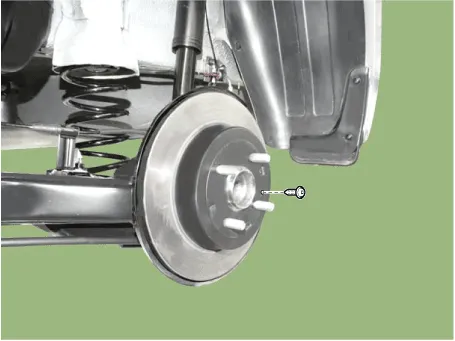
4.Loosen the screws and then remove the brake disc.
Tightening torque :4.9 - 5.9 N.m (0.5 - 0.6 kgf.m, 3.6 - 4.3 lb-ft)
5.Loosen the bolts and then remove the hub bearing.
Tightening torque :49.0 - 58.8 N.m (5.0 - 6.0 kgf.m, 36.2 - 43.4 lb-ft)
6.To install, reverse the removal procedure.
1.Loosen the wheel nuts slightly.Raise the vehicle, and make sure it is securely supported.
2.Remove the rear wheel and tire (A) from front hub.
Tightening torque :107.9 - 127.5 N.m (11.0 - 13.0 kgf.m, 79.6 - 94.0 lb-ft)

• Be careful not to damage the hub bolts when removing the rear wheel and tire.
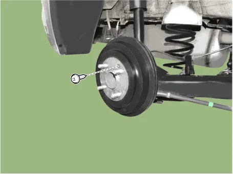
3.Loosen the screw and then remove the drum.
Tightening torque :4.9 - 5.9 N.m (0.5 - 0.6 kgf.m, 3.6 - 4.3 lb-ft)
4.Disconnect the rear wheel speed sensor connector.
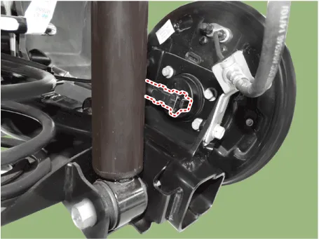
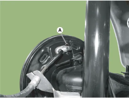
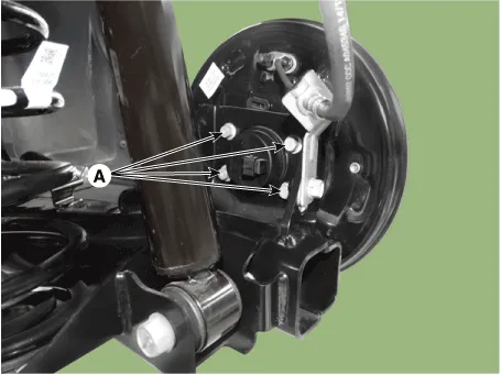
5.Loosen the hub mounting bolts (A) and then remove the hub from the torsion beam.
Tightening torque :44.1 - 53.9 N.m (4.5 - 5.5 kgf.m, 32.9 - 39.8 lb-ft)
6.To install, reverse the removal procedure.
1.Measure the output voltage between the terminal of the wheel speed sensor and the body ground.

• In order to protect the wheel speed sensor, when measuring output voltage, a 100Ω resister must be used as shown.

2.Compare the change of the output voltage of the wheel speed sensor to the normal change of the output voltage as shown below.
V_low : 0.59V - 0.84VV_high : 1.18V - 1.68VFrequency range : 1 - 2,500 Hz


Other information:
Hyundai Accent (HC) (2017 - 2022) Service Manual: Seats
Front seat 1. Forward and backward — adjust distance to pedals and steering wheel for safe control 2. Seatback angle — set a comfortable upright angle that supports your back 3. Seat height (Driver's seat) — adjust eye level for clear visibility over the hood 4. Headrest — align with the head for whiplash protection in a collision 5. Seat warmer — comfort feature for cold weather driving (if equipped) Rear seat 6.Hyundai Accent (HC) (2017 - 2022) Service Manual: Maintenance services
You should exercise the utmost care to prevent damage to your Hyundai Accent and injury to yourself whenever performing any maintenance or inspection procedures. Use proper tools, keep the engine compartment clean, and never work near moving parts with the engine running. Have your vehicle maintained and repaired by an authorized HYUNDAI dealer. An authorized HYUNDAI dealer meets HYUNDAI's high service quality standards and receives technical support from HYUNDAI in order to provide you with a high level of service satisfaction.
Contents
- Description and Operation
- Components and Components Location
- Schematic Diagrams
- Repair procedures
- Troubleshooting
- ABS Control Module
- Front Wheel Speed Sensor
- Rear Wheel Speed Sensor
Categories
- Manuals Home
- Hyundai Accent Owners Manual
- Hyundai Accent Service Manual
- Questions & Answers
- Video Guides
- Useful Resources
- New on site
- Most important about car
- Privacy Policy

0.0092