Hyundai Accent (HC): Intelligent Variable Transmission (IVT) System (Continuously Variable Transmission) / Hydraulic System
Contents:
Fluid
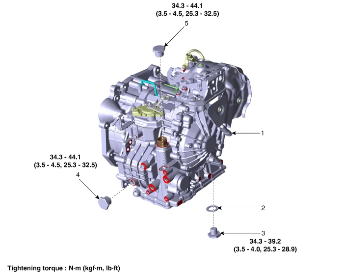
1. Intelligent Variable Transmission (IVT)
2. Drain plug gasket
3. Drain plug
4. Intelligent Variable Transmission Fluid (IVTF) level check plug
5. IVTF injection plug

• Be sure to use the genuine IVTF (SP-IVT1).
• When replacing with non-genuine IVTF, bad shift and vibration may occur, causing damage to the IVT.
• Non-genuine IVT fluid includes aftermarket IVT fluid indicated as interchangeable with genuine Hyundai fluid.
Intelligent Variable Transmission Fluid (IVTF) Level Check

• When checking the IVTF level, be careful not to allow foreign substance (like dust) to enter through the filler hole.
1.Remove the air cleaner assembly.(Refer to Engine Mechanical System - "Air cleaner")
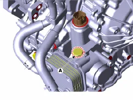
2.Add 0.3 liters of SP-CVT1 through the IVTF filler hole after removing the IVTF injection plug (A).
3.Start the engine to warm up the IVTF.

• Do not step on the brake and accelerator simultaneously to warm up the IVTF.
4.Check by using Diagnostic tool that the temperature of the IVTF is between 50°C and 60°C (122 - 140°F).
5.Move the shift lever slowly from "P" to "D", then back to "P". Repeat this sequence two times and then move the shift lever to "P" range.

• Maintain at each speed position for more than 2 sec.
6.Remove the under cover.(Refer to Engine Mechanical System - "Engine Room Under Cover")
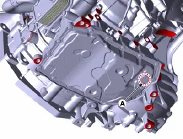
7.Lift the vehicle and remove the IVTF level plug (A) from the valve body cover.

• When removing the IVTF level plug, keep the vehicle on a level ground.

8.Check the IVTF level.
Normally: IVTF flows out in a thin oil stream.Excessive (abnormal): Over 0.4 liters of IVTF flows out for 2 minutes.Insufficient (abnormal): There is no fluid flow.

• If the IVTF level is too high or low, follow the instructions below.
• Excessive: Drain until the IVTF flows out in a thin oil stream.
• Insufficient: Add until the IVTF flows out in a thin oil stream.
9.Install the IVTF level plug (A).
Tightening torque : 34.3 - 44.1 N.m (3.5 - 4.5 kgf.m, 25.3 - 32.5 lb-ft)
10.Lower the vehicle and install the IVTF injection plug (A).
Tightening torque : 34.3 - 44.1 N.m (3.5 - 4.5 kgf.m, 25.3 - 32.5 lb-ft)


• Be sure to use the genuine IVTF (SP-IVT1).
• When replacing with non-genuine IVT fluid, bad shift and vibration may occur, causing damage to the IVT.
• Non-genuine IVT fluid includes aftermarket IVT fluid indicated as interchangeable with genuine Hyundai fluid.
1.Remove the under cover.(Refer to Engine Mechanical System - "Engine Room Under Cover")
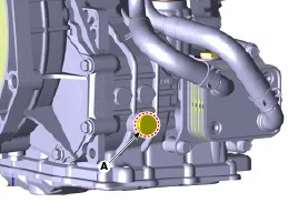
2.Remove the IVTF drain plug (A), allow the fluid to drain out and then reinstall the drain plug.
Tightening torque:34.3 - 39.2 N.m (3.5 - 4.0 kgf.m, 25.3 - 28.9 lb-ft)

• The existing IVTF drain plug gasket must be replaced with a new one. (Do not reuse it.)
3.Remove the air cleaner assembly.(Refer to Engine Mechanical System - "Air cleaner")
4.Remove the IVTF injection plug (A).

5.Fill the Intelligent Variable Transmission(IVT) with about 5.0 liters of SP-CVT1 through the IVTF filler hole.
6.Perform the IVTF level check procedure.(Refer to Fluid - "Inspection")
Valve Body
| Driven Pulley Control Valve (Secondary_VFS) / Drive Pulley Control Valve (Primary_VFS) / Line Pressure Control Valve (Line_VFS) |
|
| Item | Specification |
| Control type | N/H (Normally High) |
| Control pressure kpa (kgf/㎠, psi) | 0 - 956.14 ± 14.71 (0 - 9.75 ± 0.15, 0 - 138.68 ± 2.13) |
| Current (mA) | 0 - 1.100 |
| Coil resistance (Ω) | 5.3 ± 0.3 |
| Damper Clutch Control Solenoid Valve (Damper/C_VFS) |
|
| Item | Specification |
| Control type | N/L (Normally Low) |
| Control pressure kpa (kgf/㎠, psi) | 0 - 956.14 ± 14.71 (0 - 9.75 ± 0.15, 0 - 138.68 ± 2.13) |
| Current (mA) | 0 - 1.100 |
| Coil resistance (Ω) | 5.3 ± 0.3 |
|
| Item | Specification |
| Control type | N/H (Normally High) |
| Control pressure kpa (kgf/㎠, psi) | 0 - 1569.06 (0 - 16.00, 0 - 227.57) |
| Current (mA) | 0 - 1.100 |
| Coil resistance (Ω) | 5.3 ± 0.3 |
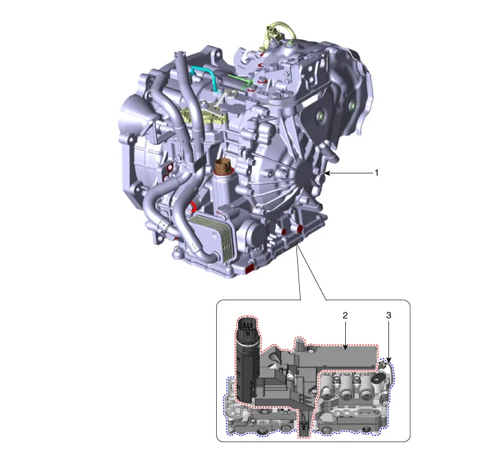
1. Intelligent Variable Transmission (IVT)
2. E-module
3. Valve body
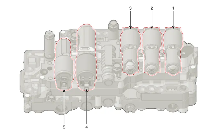
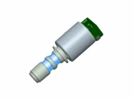
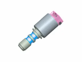
1. Drive pulley control valve (Primary_VFS)
2. Driven pulley control valve (Secondary_VFS)
3. Damper clutch control solenoid valve (Damper/C_VFS)
4. Drive/reverse clutch control solenoid valve (Clutch/Brake_VFS)
5. Line pressure control valve (Line_VFS)
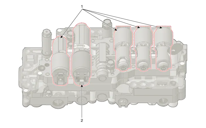
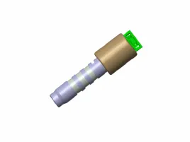
1. Indirect control solenoid
2. Direct control solenoid
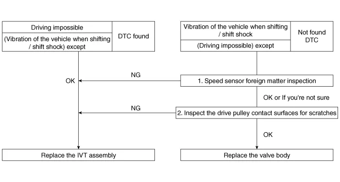
Inspection Flow
1.Disconnect the battery (-) terminal.
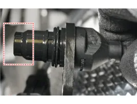
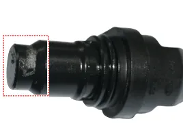
2.Remove the driven pulley speed sensor.(Refer to Intelligent Variable Transmission (IVT) System (Continuously Variable Transmission) - "Driven Pulley Speed Sensor")
3.Visually inspect the drive pulley speed sensor.

• If there are no iron on the driven pully speed sensor, replace the valve body. [OK apply]
• If there is more than 2/3 iron in the driven pully speed sensor, replace the IVT assembly. [NG apply]
| OK | NG |
|
|
1.Disconnect the battery (-) terminal.
2.Remove the valve body.(Refer to Intelligent Variable Transmission (IVT) System (Continuously Variable Transmission) - "Valve Body")
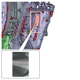
3.Inspect the drive pulley contact surfaces for scratches.

• Replace the valve body if there are no scratches on the driven pully surface. [OK apply]
• Replace the IVT assembly if there are scratches on the driven pully surface. [NG apply]
| OK | NG |
|
|


• Maintain clean condition so that foreign substance does not get into the Intelligent Variable Transmission (IVT).
• Use a coated apron, latex gloves, and stainless tray to prevent foreign substance.
• Intelligent Variable Transmission (IVT) is composed of delicate components. Be careful not to cause any damage on the component when assembling and disassembling.
1.Remove the air cleaner assembly.(Refer to Engine Mechanical System - "Air Cleaner")
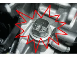
2.Disconnect the main connector (A).


• After detaching the main connector, wrap a plastic bag around the connector (A) to prevent coolant from getting into it.
• If coolant gets into the connector, corrosion may occur inside the connector (A), thus causing an open/short circuit. In this case, trouble codes and shift failure may also occur.
3.Remove the under cover.(Refer to Engine Mechanical System - "Engine Room Under Cover")
4.Remove the IVTF drain plug (A), reinstall the drain plug after allowing the fluid to drain out.
Tightening torque:34.3 - 44.1 N.m (3.5 - 4.5 kgf.m, 25.3 - 32.5 lb-ft)
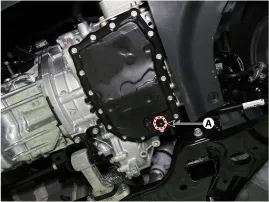

• Do not reuse Intelligent Variable Transmission Fluid(IVTF)
• The existing IVTF drain plug gasket must be replaced with a new one (do not reuse).
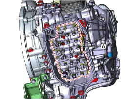
5.Remove the valve body cover (A) after removing the bolts.
Tightening torque:9.8 - 11.8 N.m (1.0 - 1.2 kgf.m, 7.2 - 8.7 lb-ft)
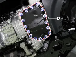

• Be careful when removing the valve body cover because the remaining IVTF remains in the valve body cover.
6.Remove the valve body gasket (A).
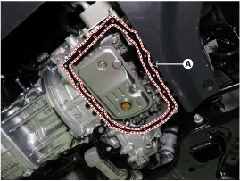
7.Remove the IVTF filter (A) after removing the bolts.
Tightening torque :9.8 - 11.8 N.m (1.0 - 1.2 kgf.m, 7.2 - 8.7 lb-ft)
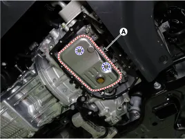
8.Disconnect the driven pulley pressure sensor connector (A).
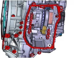
9.Remove the IVT valve body (A) after removing the bolts.
Tightening torque :9.8 - 11.8 N.m (1.0 - 1.2 kgf.m, 7.2 - 8.7 lb-ft)
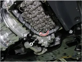
1.To install, reverse the removal procedures.

• Before installing the valve body, check the O-ring (A) is installed.
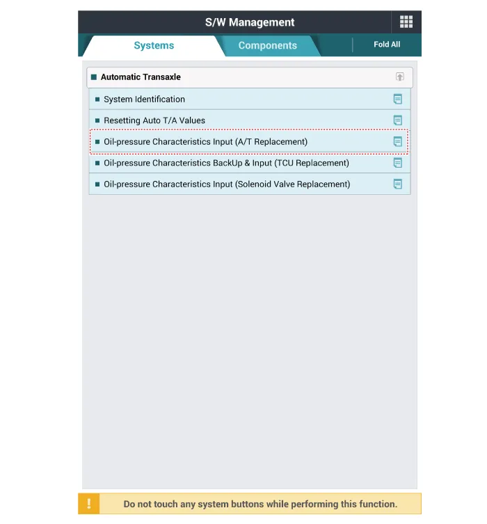
(1)Clear the diagnostic trouble codes (DTC) using the diagnostic tool. Disconnecting the battery negative terminal will not clear the DTCs. Clear DTCs using the diagnostic tool at all times.

• Even though disconnecting the battery negative terminal, the DTCs will not be cleared. So, be sure to clear the DTCs using the diagnostic tool.
(2)Reset the intelligent variable transmission adaptive values using the diagnostic tool.

(3)Perform the hydraulic characteristics input procedure using the diagnostic tool.
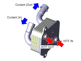
IVTF Warmer
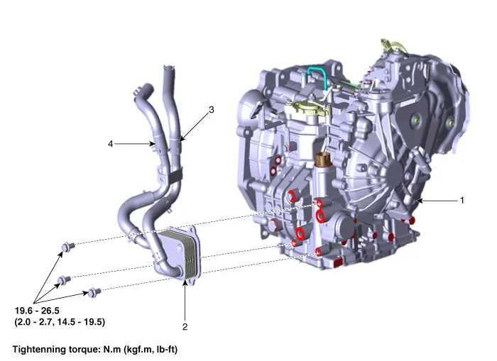
1. Intelligent Variable Transmission (IVT)
2. IVTF warmer
3. Coolant hose (IN)
4. Coolant hose (OUT)
• Prevents overheating of the transmisson fluid while the vehicle is moving.
• Transaxle fluid warm-up and cooling can be done with a single system.
1.Remove the under cover.(Engine Mechanical System - "Engine Room Under Cover")
2.Drain the coolant.(Refer to Engine Mechanical System - "Coolant")
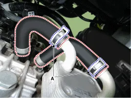
3.Separate the coolant hoses (A) from the Intelligent Variable Transmission Fluid (IVTF) warmer.
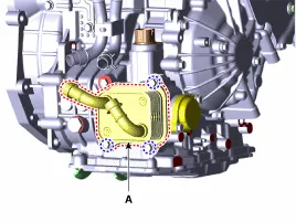
4.Loosen the bolts and then removing the IVTF warmer (A).
Tightenning torque :19.6 - 26.5 N.m(2.0 - 2.7 kgf.m, 14.5 - 19.5 lb-ft)
1.To install, reverse the removal procedures.

• Carefully install the clamp not to damage the hose.
• Install the clamp in a correct direction not to be interfered with other parts.
• After the installation, start the engine and then check if there are any leakages from the hose.
• Then finish check the IVTF level procedure and refil the IVT fluid.(Refer to Hydraulic System - "Fluid")
• Injection the coolant.(Refer to Engine Mechanical System - "Coolant")


Other information:

Contents
Categories
- Manuals Home
- Hyundai Accent Owners Manual
- Hyundai Accent Service Manual
- Questions & Answers
- Video Guides
- Useful Resources
- New on site
- Most important about car
- Privacy Policy

0.0048