Hyundai Accent (HC): Body Electrical System / Fuses And Relays
Contents:
- Components and Components Location
- Junction Box (Engine Compartment)
- Junction Box (Passenger Compartment)
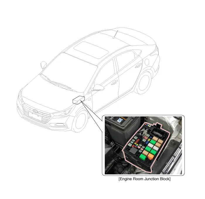
Components and Components Location
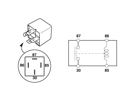
[Passenger Compart Relay]

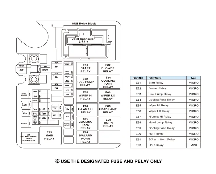
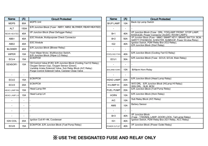
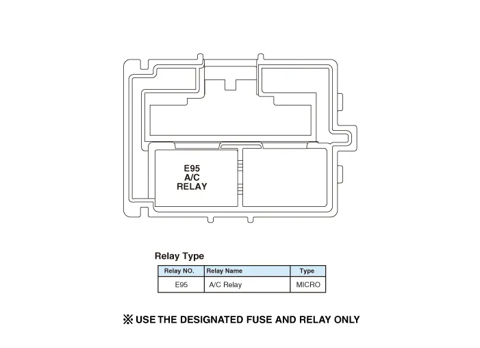
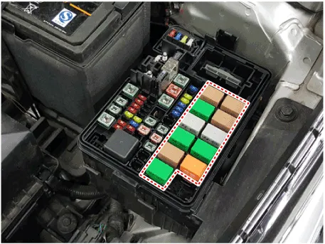
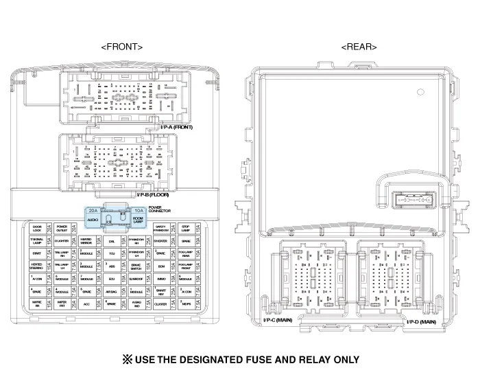
Junction Box (Engine Compartment)
1.Disconnect the negative (-) battery terminal.
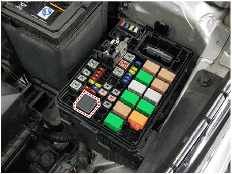
2.Pull out the relay from the engine compartment relay block.
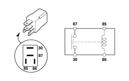
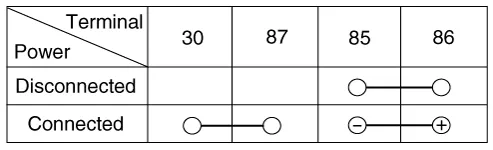
3.Check for continuity between the terminals.
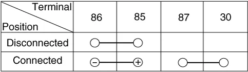
1)After supplying power to between No. 85 and 86 power relay terminals, check that there is continuity between No. 30 and 87 terminals.
2)After disconnecting power between No. 85 and 86 power relay terminals, check that there is no continuity between No. 30 and 87 terminals.
1.Be sure there is no play in the fuse holders, and that the fuses are held securely.
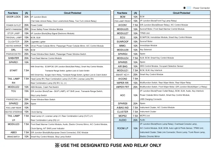
2.Are the fuse capacities for each circuit correct?
3.Are there any blown fuses?If a fuse is to be replaced, be sure to use a new fuse of the same capacity. Always determine why the fuse blew first and completely eliminate the problem before installing a new fuse.

ŌĆō Multi fuse is needed to replace in the mass when it damaged only one fuse.
ŌĆō When replace the multi fuse, refer to the "Engine compartment - component location" diagram exactly.
ŌĆō Use the multi fuse capacities for each circuit correctly.
Junction Box (Passenger Compartment)
1.Be sure there is no play in the fuse holders, and that the fuses are held securely.
2.Are the fuse capacities for each circuit correct?
3.Are there any blown fuses?If a fuse is to be replaced, be sure to use a new fuse of the same capacity. Always determine why the fuse blew first and completely eliminate the problem before installing a new fuse.
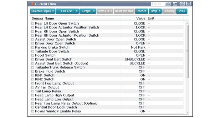
1.The Interior Junction Block can be diagnosed by using the GDS. The Interior Junction Block communicates with the GDS which then displays inputs and outputs along with codes.
2.To diagnose the Interior Junction Block function, select the vehicle model, Interior.
3.To consult the present input/out value of Interior Junction Block, "Current DATA". It provides information of Interior Junction Block input/output conditions.
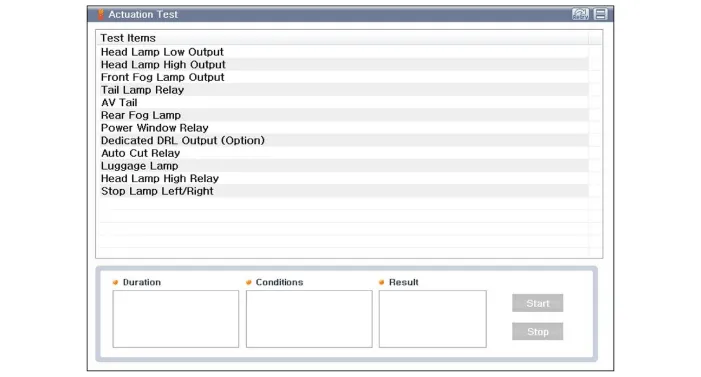
4.To perform functional test on Interior Junction Block outputs, select "Actuation Test"
1.Disconnect the negative(-) battery terminal.
2.Remove the crash pad lower panel.(Refer to Body - "Crash Pad Lower Panel")
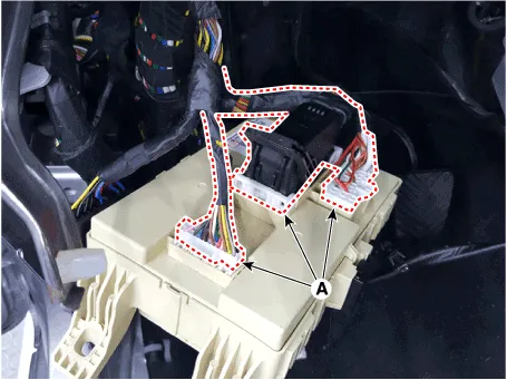
3.Disconnect the connectors (A) from the fuse side of the junction block.
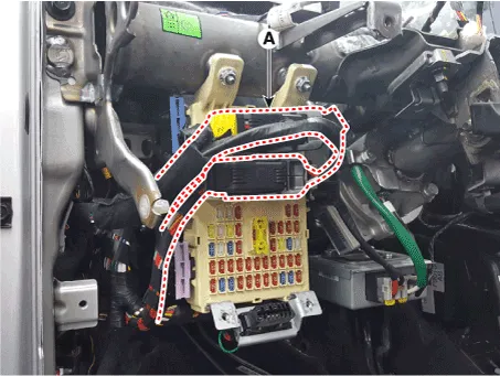
4.Remove the junction block (A) after loosening the mounting nuts.
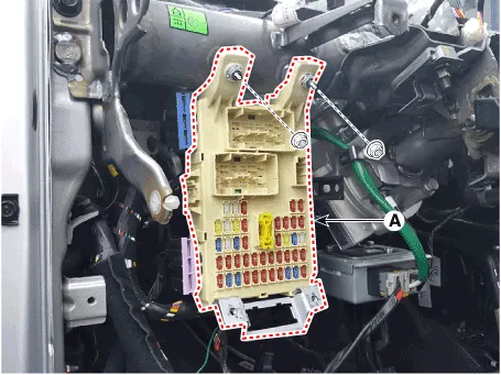
5.Disconnect the connectors (A) from the back side of the junction block.
1.Install the Interior junction block.
2.Install the crash pad lower panel.
3.Check that all system operates normally.


Other information:
Hyundai Accent (HC) (2017 - 2022) Service Manual: Repair procedures
- Inspection Inspection Item ŌĆó Battery efficiency inspection ŌĆó Battery voltage inspection ŌĆó Charging voltage insptection ŌĆó General inspection ŌĆó Terminal tightening state inspection ŌĆó Engine/ transaxle ground state inspection ŌĆó Wiring harness ground state inspection ŌĆó Electrical Specified Value Inspection ŌĆó Vehicle parasitic current inspection ŌĆó Battery capacity inspection Battery Efficiency Inspection ŌĆó Check that the battery cables are connected to the correct terminals.Forward Collision-Avoidance Assist is designed to help reduce or help avoid accident risk. It recognizes the distance to the vehicle ahead through sensors (for example, radar), and, if necessary, warns the driver or applies emergency braking. ŌØł Radar type FCA does not recognize for pedestrians in front. WARNING Forward Collision-avoidance Assist is a supplemental system and is not a substitute for safe driving practices.
Contents
- Components and Components Location
- Junction Box (Engine Compartment)
- Junction Box (Passenger Compartment)
Categories
- Manuals Home
- Hyundai Accent Owners Manual
- Hyundai Accent Service Manual
- Questions & Answers
- Video Guides
- Useful Resources
- New on site
- Most important about car
- Privacy Policy

0.0073