Hyundai Accent (HC): Body Electrical System / Indicators And Gauges
Contents:
Instrument Cluster
Standard
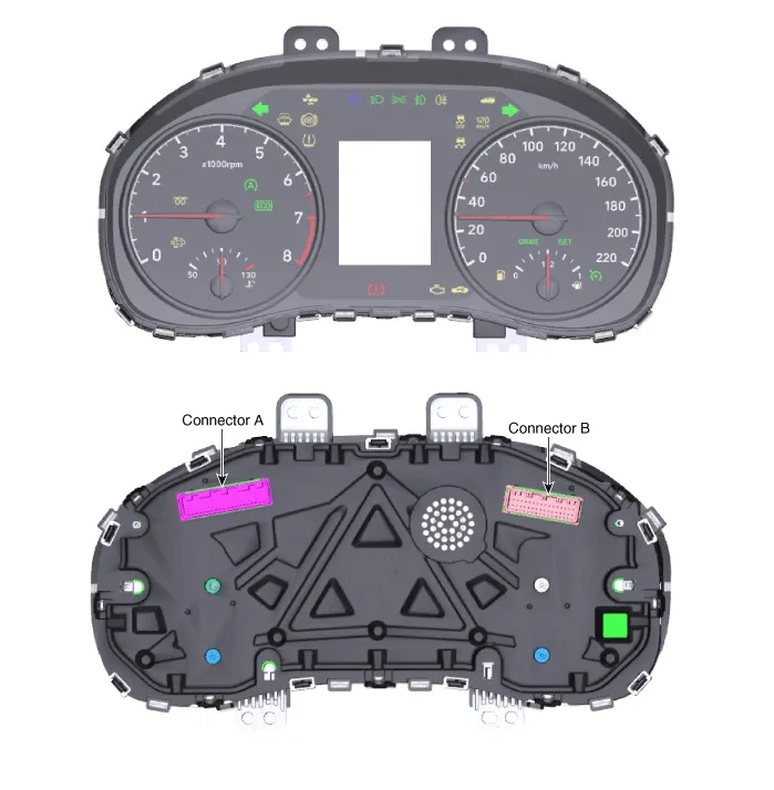
Supervision
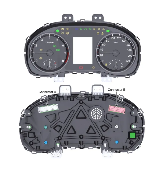
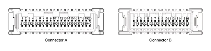
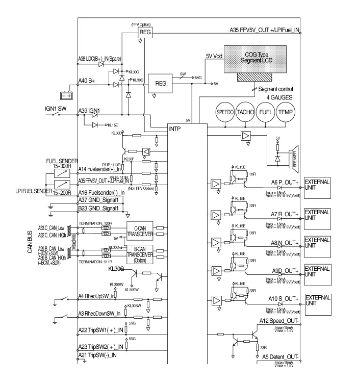
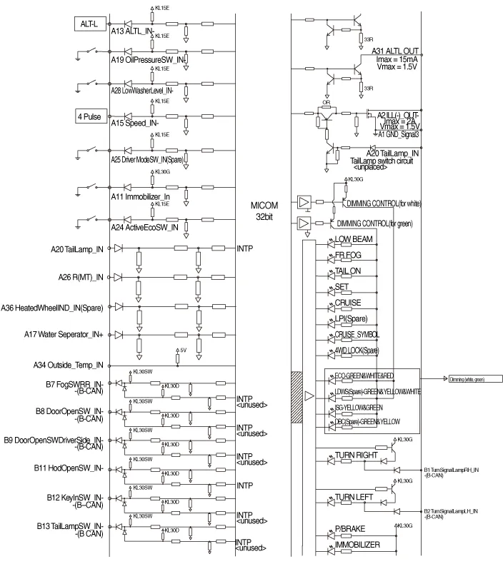
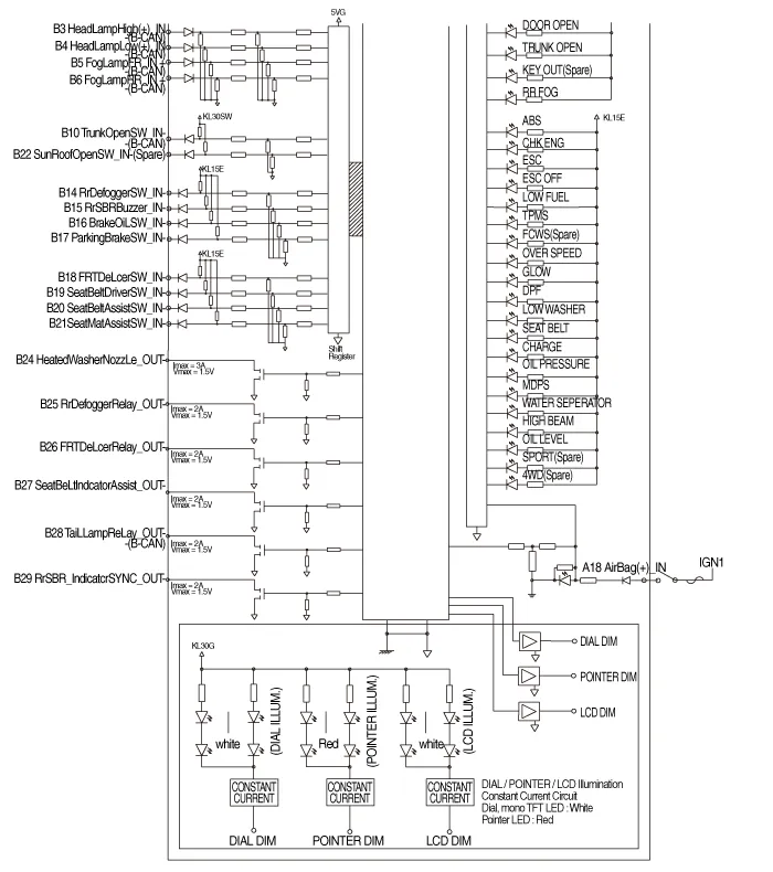
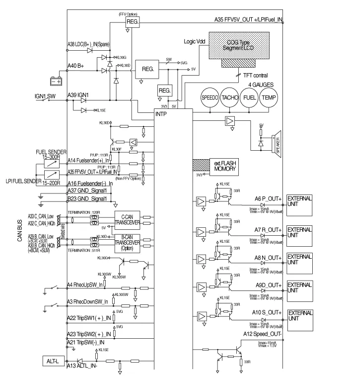
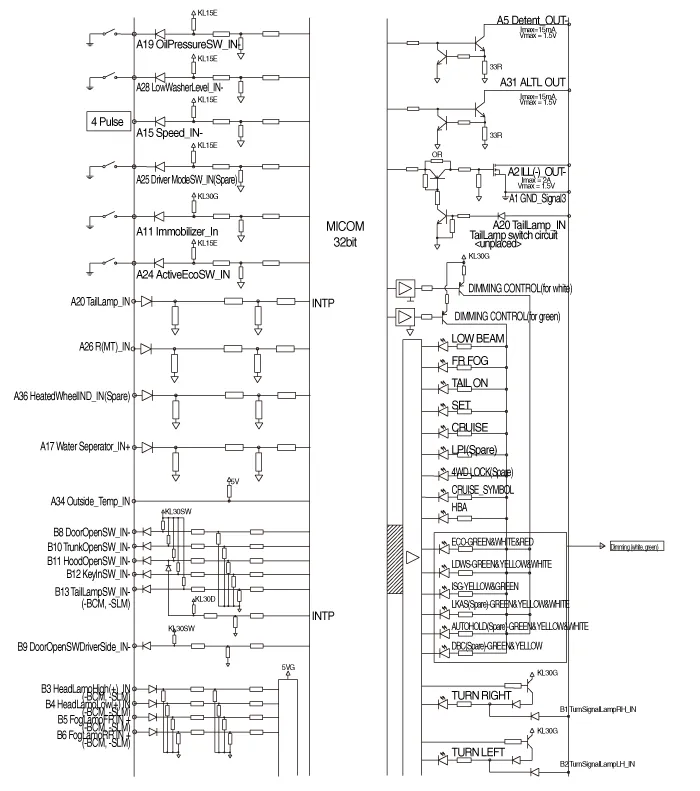
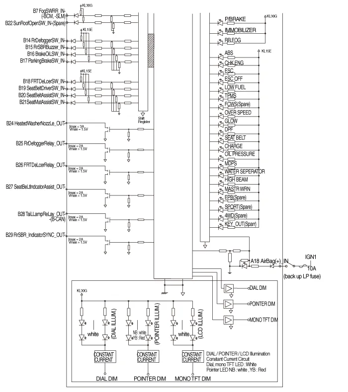
Connector Pin Information
| No | Description | No | Description | ||
| Connector A | Connector B | Connector A | Connector B | ||
| 1 | Ground signal 3 | Turnsignal lamp_Right input | 21 | Trip switch (-) | Assist seat mat switch input |
| 2 | Illumination (-) | Turnsignal lamp_left input | 22 | Trip switch1 (+) | Sunroof open switch input |
| 3 | Rheostat switch (Down) input | Head lamp high (+) | 23 | Trip switch2 (+) | Ground signal 1 |
| 4 | Rheostat switch (Up) input | Head lamp low (+) | 24 | Sport Swtich input | Heated washer nozzle output |
| 5 | Detent output | Front fog lamp (+) | 25 | Driver mode switch input | Rear defogger relay output |
| 6 | AT ('P' position) | Rear fog lamp (+) | 26 | R (MT) input | Heated glass relay output |
| 7 | AT ('R' position) | Rear fog lamp switch (+) | 27 | - | Assist seat belt indicator output |
| 8 | AT ('N' position) | Door open switch | 28 | Low washer level input | Tail lamp relay output |
| 9 | AT ('D' position) | Driver side door open switch (+) | 29 | B CAN (Low) | Rear SBR indicator SYNC output |
| 10 | AT ('S' position) | Trunk open switch (-) | 30 | B CAN (High) | - |
| 11 | Immobilizer input | Hood open switch (-) | 31 | Alternator Output | - |
| 12 | Vehicle speed output | Key in switch (-) | 32 | C CAN (High) | - |
| 13 | Alternator input | Tail lamp switch (-) | 33 | C CAN (Low) | |
| 14 | Fuel sender input | Rear defogger switch input | 34 | Outsidetemp input | |
| 15 | Vehicle speed input | Rear SBR buzzer input | 35 | FFV 5V output / LPI Fuel input | |
| 16 | Fuel sender input | Brake oil switch | 36 | Heated wheel indicator input (NAS Only) | |
| 17 | Water seperator input | Parking brake switch input | 37 | Ground signal | |
| 18 | Airbag input | Heated glass switch input | 38 | LDC (+) input | |
| 19 | Oil pressure switch input | Seat belt driver switch input | 39 | IGN (+) | |
| 20 | Tail lamp input | Seat belt assist switch input | 40 | Battery (+) | |
[Standard]
[Supervision]
1.Disconnect the negative (-) battery terminal.
2.Remove the cluster fascia panel.(Refer to Body - "Cluster Fascia Panel")
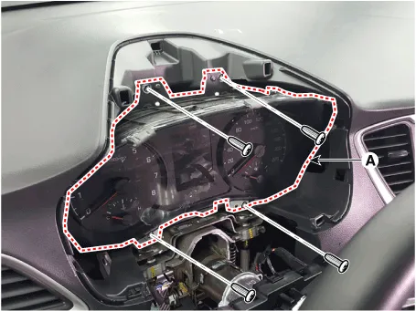
3.Remove the cluster (A) from the housing after loosening the mounting screws.
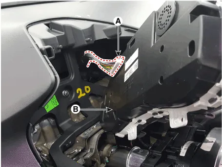
4.Disconnect the cluster connecter (A) and then remove the cluster (B).
1.Connect the cluster connector.
2.Install the cluster assembly.
3.Install the cluster facia panel.
4.Connect the negative (-) battery terminal.
1.Check point (Warning indicator)cator)

No | Ref Symbol | Name | Color | Signal input | Signal Control (Unit / Sensor) | Check point | ||||||
| 1 |
| Turnsignal Lamp (Left) | Green | B-CAN | BCM |
| ||||||
| 2 |
| Turnsignal Lamp (Right) | Green | B-CAN | BCM |
| ||||||
| 3 |
| Front Fog Lamp | Green | B-CAN | BCM |
| ||||||
| 4 |
| Tail Lamp | Green | B-CAN | BCM |
| ||||||
| 5 |
| High Beam | Blue | B-CAN | BCM |
| ||||||
| 6 |
| Rear Fog lamp | Yellow | B-CAN | BCM |
| ||||||
| 7 |
| Tail gate open | Yellow | B-CAN | BCM |
| ||||||
| 8 |
| Immobilizer | Yellow | Hard-wired | Immobilizer Unit |
| ||||||
| 9 |
| ABS | Yellow | C-CAN | ABS TCS |
| ||||||
| 10 |
| ESC | Yellow | C-CAN | TCS |
| ||||||
| 11 |
| ESC OFF | Yellow | C-CAN | TCS |
| ||||||
| 12 |
| Check Engine | Yellow | C-CAN | ECM |
| ||||||
| 13 |
| Fuel Low | Yellow | Hard-wired | Fuel sender |
| ||||||
| 14 |
| TPMS | Yellow | CAN | TPMS |
| ||||||
| 15 |
| AUTO STOP | Green Yellow | CAN | ECM |
| ||||||
| 16 |
| Seat belt | Red | Hord-wind | Seat belt Switch |
| ||||||
| 17 |
| Door Open | Red | B-CAN | BCM |
| ||||||
| 18 |
| ABS Parking Brake Brake Fluid | Red | C-CAN | ABS TCS |
| ||||||
| B-CAN | BCM Park brake switch |
| ||||||||||
| 19 |
| Air Bag | Red | C-CAN | SRSCM |
| ||||||
| 20 |
| Alternator (Battery Charge) | Red | Hard-wired | Alternator |
| ||||||
| 21 |
| Oil Pressure | Red | Hard-wired | Oil Pressure switch |
| ||||||
| 22 |
| EPS (MDPS) | Red | C-CAN | MDPS |
|


2.Check the gauge functionality refer to below information when gauge has a problem
| No | Gauge | Input type | Input source | Check point |
| 1 | Speed gauge | CAN | ABS (ESC) | CAN failure |
| Hardwire | Speed Sensor | Vehicle Speed input | ||
| 2 | Tacho gauge | CAN | ECM | ECM CAN failure |
| 3 | Coolant temp gauge | CAN | ECM | ECM CAN failure |
| 4 | Fuel gauge | Hardwire | Fuel sender | Fuel sender (Wiring failue) |
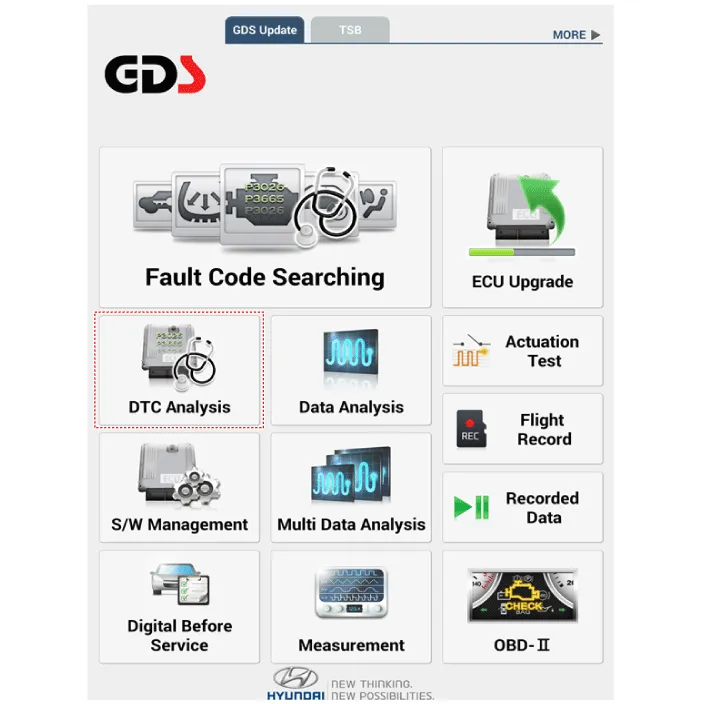
1.In the body electrical system, failure can be quickly diagnosed by using the vehicle diagnostic system (Diagnostic tool).The diagnostic system (Diagnostic tool) provides the following information.
(1)Fault Code Searching : Checking failure and code number (DTC)
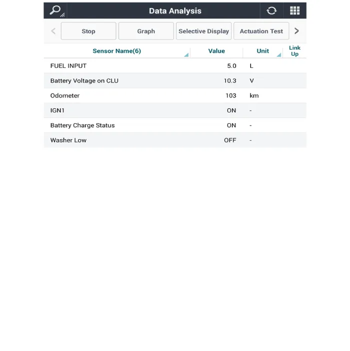
(2)Data Analysis : Checking the system input/output data state
(3)Actuation test : Checking the system operation condition
(4)S/W Management : Controlling other features including system option setting and zero point adjustment
2.If diagnose the vehicle by Diagnostic tool, select "DTC Analysis" and "Vehicle".
3.If check current status, select the "Data Analysis" and "Car model".
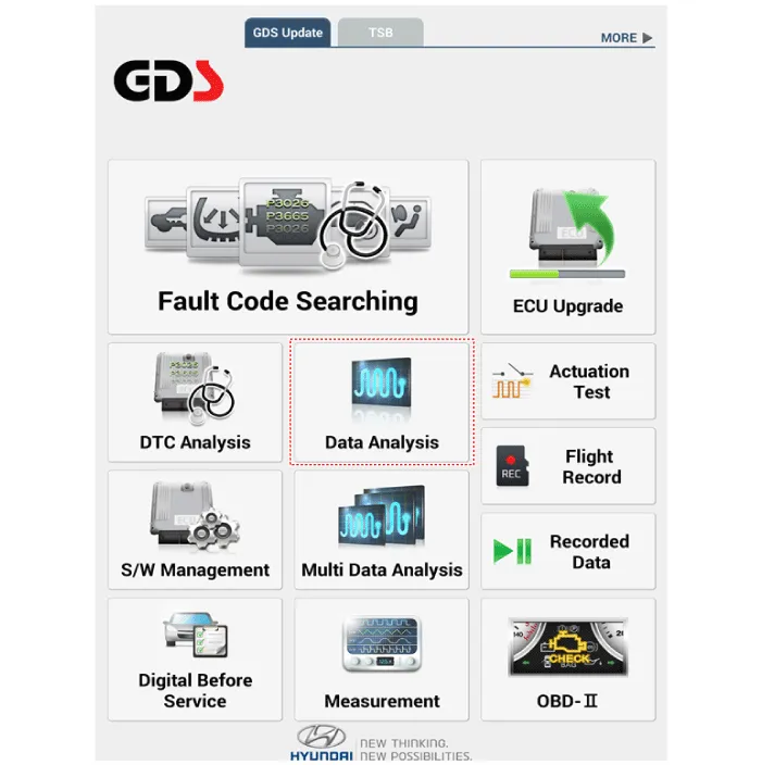
4.Select the 'CLU' to search the current state of the input/output data.
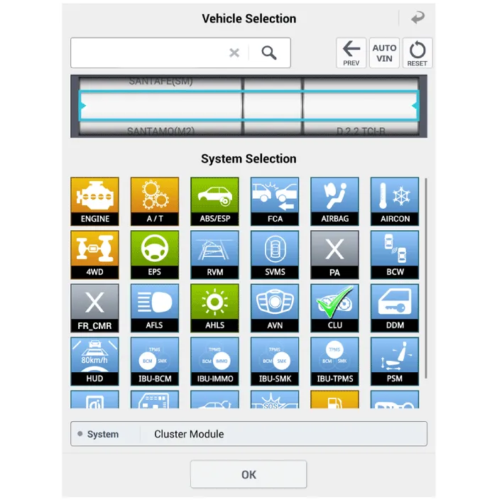
1.Connect the cable of Diagnostic tool to the data link connector in driver side crash pad lower panel.
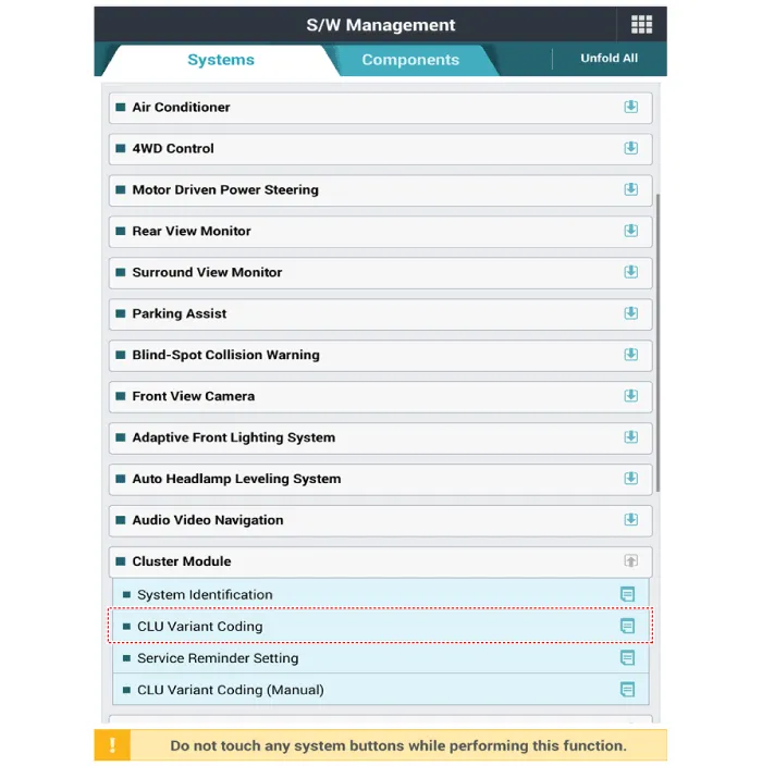
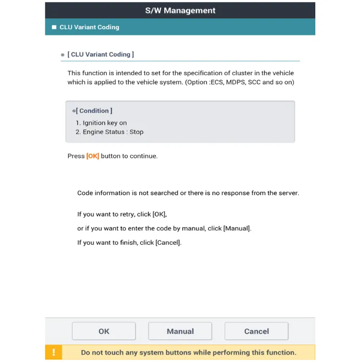
2.Select the 'S/W Management' and 'Car model'.

3.Select the 'Cluster Module' and 'CLU Variant Coding'.


Other information:
Hyundai Accent (HC) (2017 - 2022) Service Manual: Inside Rearview Mirror
Before you start driving, adjust the inside rearview mirror to center the view through the rear window. A correctly adjusted mirror in your Hyundai Accent helps you maintain safe awareness of traffic behind you without needing to change your seating position. WARNING Make sure your line of sight is not obstructed. Do not place objects in the rear seat, cargo area, or behind the rear headrests that could interfere with your vision through the rear window.Hyundai Accent (HC) (2017 - 2022) Service Manual: Specifications
- Specifications DescriptionSpecificationsLimit General TypeIn-line, DOHC   Number of cylinders4   Bore75.60 mm (2.9764 in)   Stroke89.0 mm (3.5039 in.)  Total displacement1,598 cc (97.52 cu.in)  Compression ratio11.2 ± 0.2 : 1  Firing order1-3-4-2   Valve timing Intake valveOpensBTDC 42° - ATDC 38°   ClosesABDC 7° - ABDC 87°   Exhaust valveOpensBBDC 43° - ABDC 2°   ClosesATDC 0° - ATDC 45°   Cylinder head Flatness of gasket surfaceLess than 0.
Contents
Categories
- Manuals Home
- Hyundai Accent Owners Manual
- Hyundai Accent Service Manual
- Questions & Answers
- Video Guides
- Useful Resources
- New on site
- Most important about car
- Privacy Policy

0.0091