Hyundai Accent (HC): Body Electrical System / Power Door Locks
Contents:
Components and Components Location
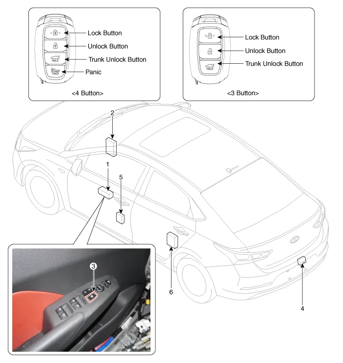
1. Driver power window main switch
2. Body Control Module (BCM)
3. Door look switch
4. Tailgate lock actuator
5. Front door lock actuator
6. Rear door lock actuator
Power Door Lock Actuators
1.Remove the front door trim.(Refer to Body - "Front Door Trim")
2.Remove the front door module.(Refer to Body - "Front Door Module")
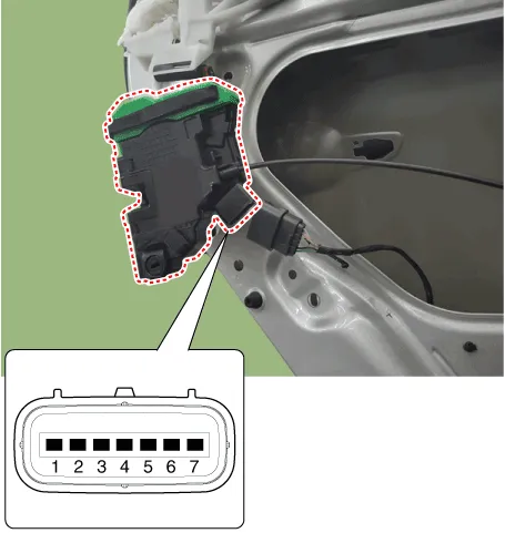
3.Disconnect the connectors from the actuator.
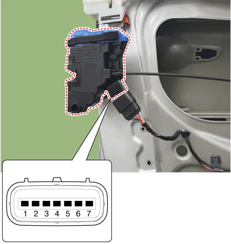
| No | Pin Information | |
| LH | RH | |
| 1 | Motor 1 | Lock / UnLock switch |
| 2 | Motor 2 | COM |
| 3 | - | Key Lock switch |
| 4 | Key Unlock switch | Key Unlock switch |
| 5 | Key Lock switch | - |
| 6 | COM | Motor 2 |
| 7 | Lock / UnLock switch | Motor 1 |
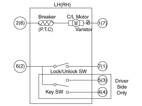
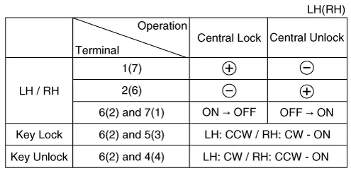
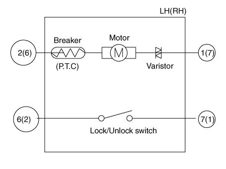
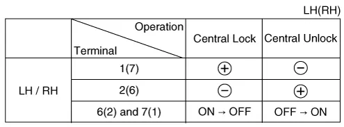
4.Check actuator operation by connecting power and ground according to the table. To prevent damage to the actuator, apply battery voltage only momentarily.
1.Remove the rear door trim.(Refer to Body - "Rear Door Trim")
2.Remove the rear latch.(Refer to Body - "Rear Door Latch")
3.Disconnect the connectors from the actuator.
| No | Pin Information | |
| LH | RH | |
| 1 | Motor 1 | Lock / UnLock switch |
| 2 | Motor 2 | COM |
| 3 | - | - |
| 4 | - | - |
| 5 | - | - |
| 6 | COM | Motor 2 |
| 7 | Lock / UnLock switch | Motor 1 |
4.Check actuator operation by connecting power and ground according to the table. To prevent damage to the actuator, apply battery voltage only momentarily.
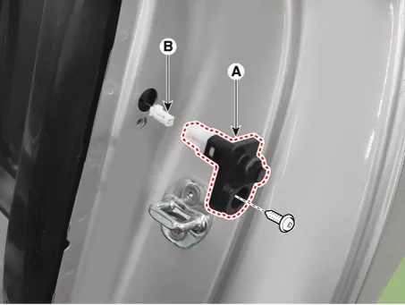
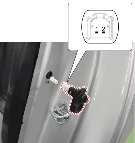
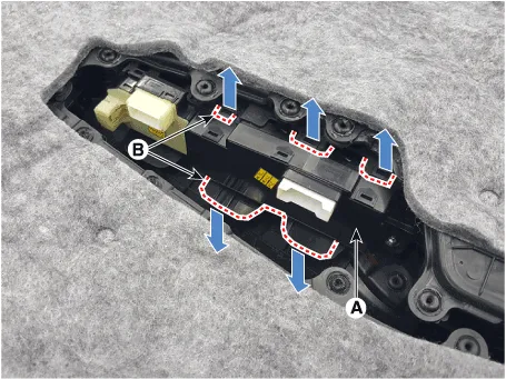
1.Remove the door switch (A) after loosening the screw and disconnecting the connector (B).
2.Check for continuity between the terminals in each switch position according to the table.
1.Remove the tailgate trim. (Refer to Body - "Tailgate Trim")
2.Disconnect the connector from the actuator.
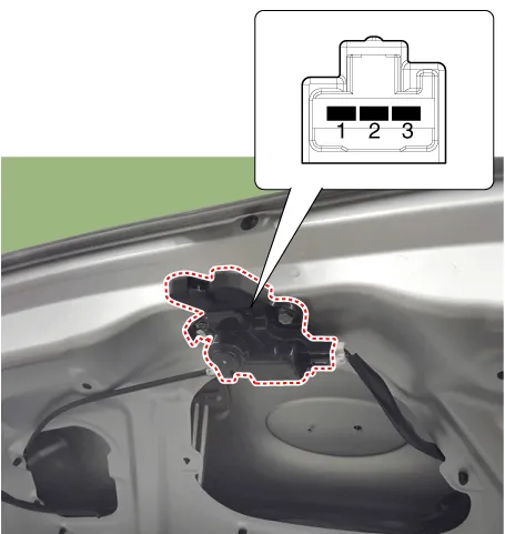
3.Check for continuity between the terminals in each switch position according to the table.

4.Check actuator operation by connecting power and ground according to the table. To prevent damage to the actuator, apply battery voltage only momentarily.

Power Door Lock Switch
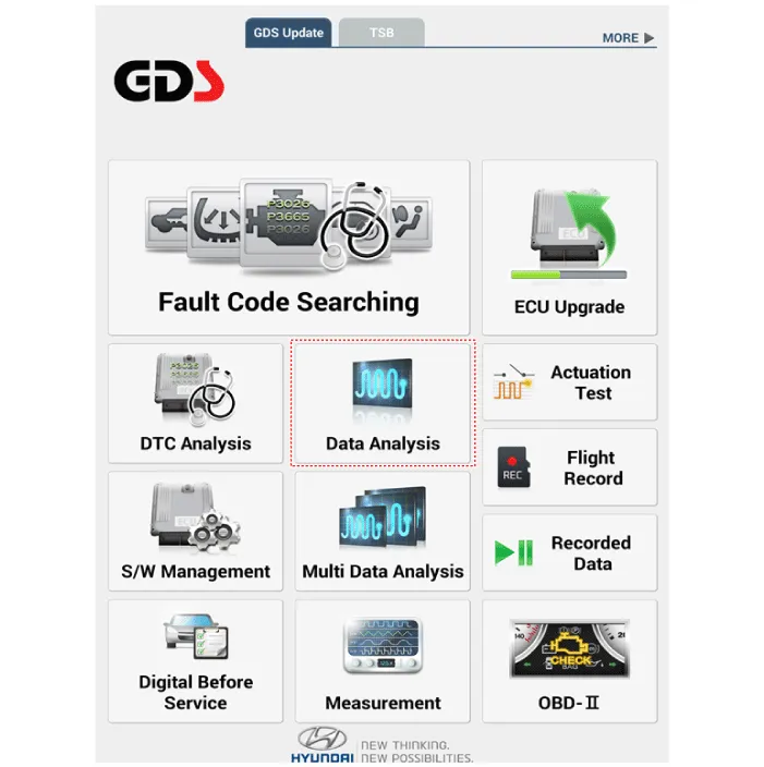
1.In the body electrical system, failure can be quickly diagnosed by using the vehicle diagnostic system (Diagnostic tool).The diagnostic system (Diagnostic tool) provides the following information.
(1)Fault Code Searching : Checking failure and code number (DTC)
(2)Data Analysis : Checking the system input/output data state
(3)Actuation test : Checking the system operation condition
(4)S/W Management : Controlling other features including system option setting and zero point adjustment
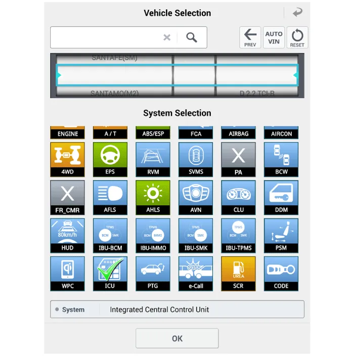
2.If diagnose the vehicle by Diagnostic tool, select "DTC Analysis" and "Vehicle".
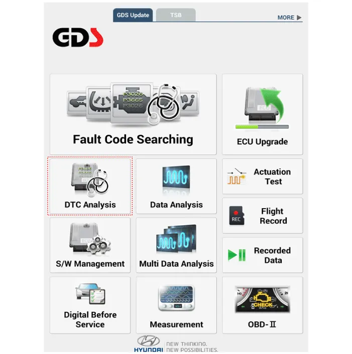
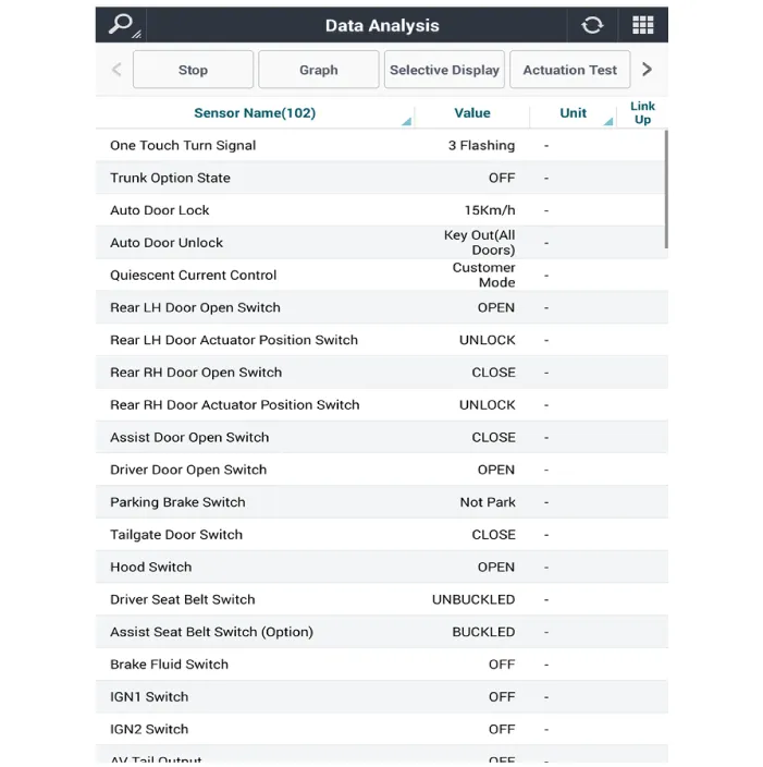
3.If check current status, select the "Data Analysis" and "Car model".
4.Select the 'ICU' to search the current state of the input/output data.
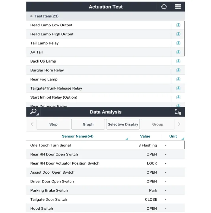
5.To forcibly actuate the input value of the module to be checked, select option 'Actuation Test'.
1.Disconnect the negative (-) battery terminal.
2.Remove the front door trim.(Refer to Body - "Front Door Trim")
3.Remove the power window switch assembly (A) by pulling out both ends of the switch holders (B).
1.Install the power window switch assembly.
2.Install the front door trim after connect the connector.


Other information:
Your Hyundai Accent electrical system is protected from electrical overload by fuses. A fuse is designed to open the circuit if current becomes excessive, helping to prevent wiring damage and protecting electrical components. This vehicle has 2 (or 3) fuse panels depending on equipment: one located in the driver’s side panel bolster and another in the engine compartment near the battery.
Contents
Categories
- Manuals Home
- Hyundai Accent Owners Manual
- Hyundai Accent Service Manual
- Questions & Answers
- Video Guides
- Useful Resources
- New on site
- Most important about car
- Privacy Policy

0.0065