Hyundai Accent (HC): Body Electrical System / Power Door Mirrors
Contents:
Components and Components Location
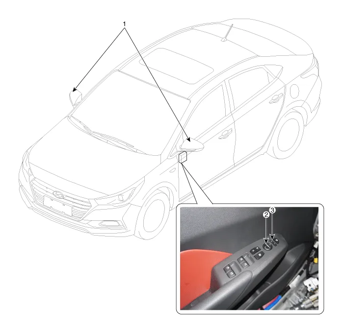
1. Power door mirror
2. Power door mirror switch
3. Power door mirror contral (LH/RH)
Power Door Mirror Switch
1.Disconnect the negative (-) battery terminal.
2.Remove the front left door trim.(Refer to Body - "Front Door Trim")
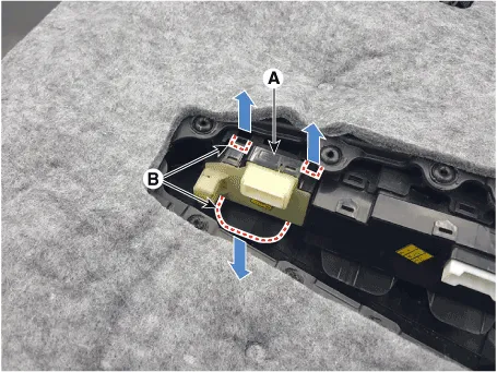
3.Remove the door mirror switch assembly (A) by pulling out both ends of the switch holders (B).
1.Install the power mirror switch.
2.Install the front door trim after connecting the connector.
3.Connect the negative (-) battery terminal.
1.Remove the front left door trim.(Refer to Body - "Front Door Trim")
2.Remove the power mirror switch (A) from the door trim.
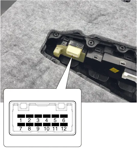
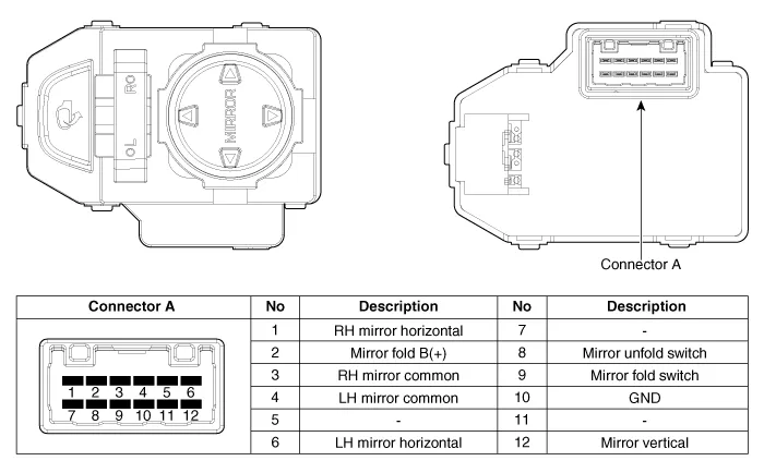
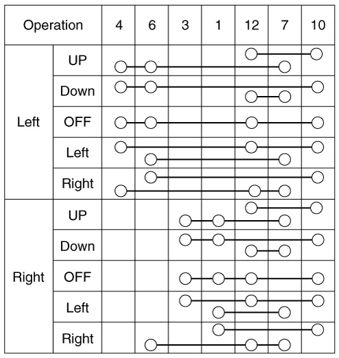
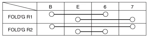
3.Check for continuity between the terminals in each switch position according to the table.
Power Door Mirror Actuator
1.Disconnect the negative (-) battery terminal.
2.Using a screwdriver or remover, remove the front door quadrant inner cover (A).

3.Disconnect the tweeter speaker connector (A).
4.Using a screwdriver or remover, remove the outside rear view mirror cover (A).

5.Disconnect the outside rear view mirror connector (A).

6.After loosening the mounting bolts, remove the outside rear view mirror (A).

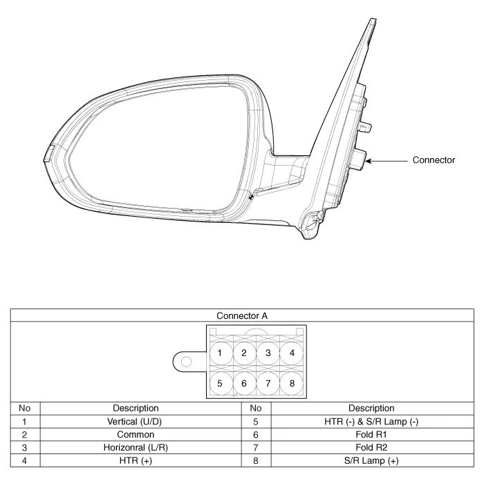
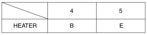
7.Apply battery voltage to each terminal as shown in the table and verify that the mirror operates properly.


1.Disconnect the negative (-) battery terminal.
2.Remove door mirror assembly.(Refer to Body - "Mirror")
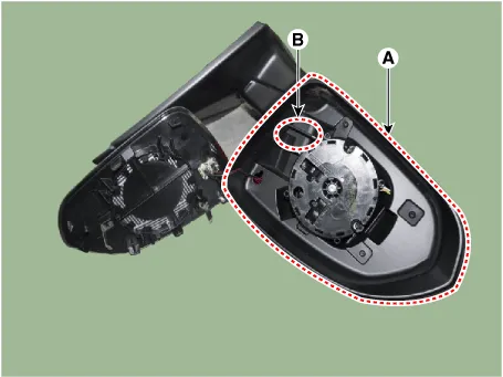
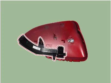
3.Remove mirror (A) to the direction as shown in the picture using (-) screw driver.

• Protect mirror from removing tool with cloth (B) wrapped.
• Be careful not to damage mirror and mirror housing during removing process.
• Apply force around the center of mirror because to apply force the end of mirror will break it. .

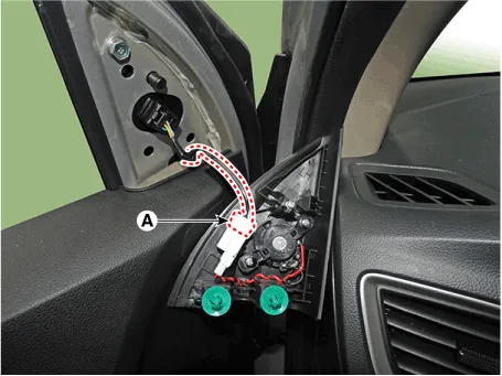
4.Remove the mirror (A) after disconnecting the heat wire connectors (B).
5.Attach protection tape at the end of the screw driver.

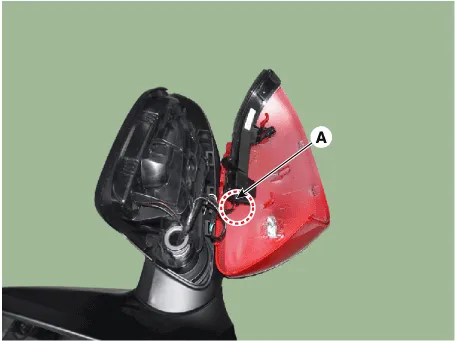
6.Insert screw driver in (A) where you can see the back of scalp.


• When inserting screw driver, avoid to touch internal wires in the mirror housing.
7.Strike down door mirror assembly in holding door mirror assembly with one hand grabbing screw driver with other hand.


• It is the way that screw driver strikes inner side of skalp cover to remove.
• Lift screw driver and door mirror assembly about 20cm height from floor then smash them vertically.
• Scalp is thrown and removed because screw driver push the back of scalp cover to remove.
8.Disconnect the LED side repeater lamp connector (A).
9.Check any damage on clip and hook at the back of scalp.
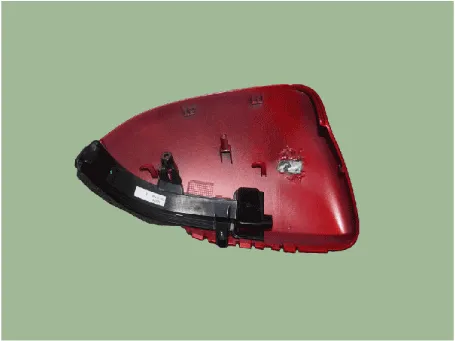

• when clip and hook are damaged, scalp lock problems(water tight, rattling noise) can occur so replace with new product.
10.Loosen the the mounting screws from LED side repeater lamp.
1.Install the LED side repeater lamp.
2.Install the front cover.
3.Install the scalp cover.
4.Connect the mirror heat wire connector then mount mirror.
5.install the door mirror assembly.
6.Connect (-) battery terminal then check if door mirror lamp works normally.


Other information:
Hyundai Accent (HC) (2017 - 2022) Service Manual: Fuses
Your Hyundai Accent electrical system is protected from electrical overload by fuses. A fuse is designed to open the circuit if current becomes excessive, helping to prevent wiring damage and protecting electrical components. This vehicle has 2 (or 3) fuse panels depending on equipment: one located in the driver’s side panel bolster and another in the engine compartment near the battery.Hyundai Accent (HC) (2017 - 2022) Service Manual: Description and Operation
- Description The SMART KEY system is a system that allows the user to access and operate a vehicle in a very convenient way. To access the vehicle, no traditional key or remote control unit is needed.The user carries a SMART KEY FOB which does not require any conscious actions by the user (e.g. operate a RKE button). The SMART KEY system is triggered by pressing a push button in the door handle.
Contents
Categories
- Manuals Home
- Hyundai Accent Owners Manual
- Hyundai Accent Service Manual
- Questions & Answers
- Video Guides
- Useful Resources
- New on site
- Most important about car
- Privacy Policy

0.0069