
Hyundai Accent (HC): Body Electrical System / Power Windows
Contents:
Components and Components Location
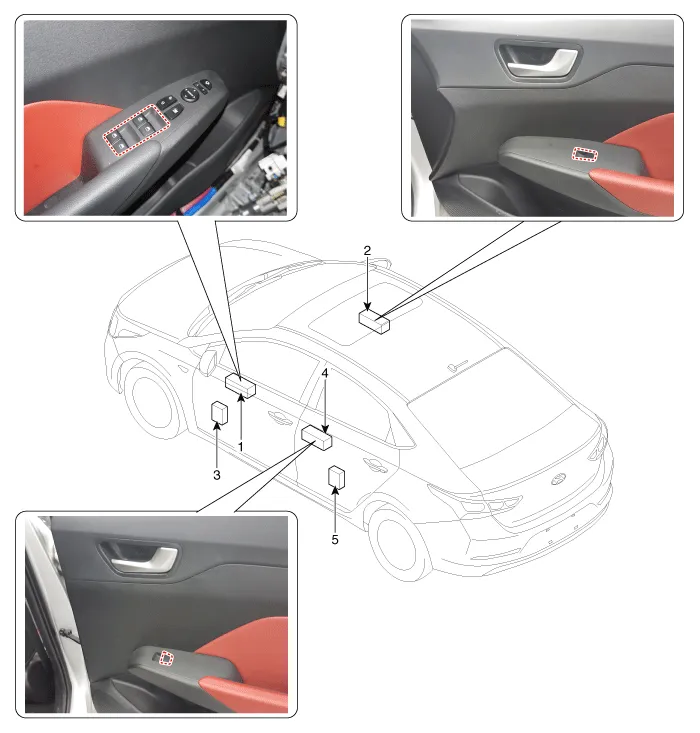
1. Drive power window main switch
2. Passenger power window main switch
3. Front window motor
4. Rear window switch
5. Rear window motor
Description and Operation
1.Safety function conditionWhen detect the force of 100N (using the 10N/mm spring) during the window rising, window is reversed.
2.Length of window reversing (except holding the auto-up switch)
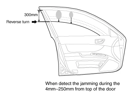
– When detect the jamming during the 4mm - 250mm from top of the door.→ Window is reversed until 300mm from top of the door.
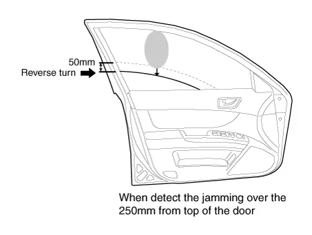
– When detect the jamming over the 250mm from top of the door.→ Window is reversed until 50mm from jamming position.
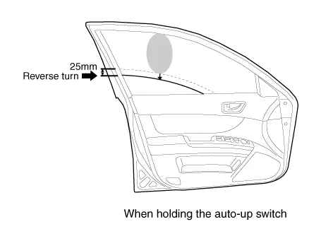
3.Length of window reversing (holding the auto-up switch)
– When detect the jamming during holding the auto-up switch.→ Window is reverse until 25mm from jamming position.
– Auto-up function is not available during the 5 seconds from above condition.→ When holding the auto-up switch, window is operated as a manual-up function. (Safety function is not activated.)
– When holding the auto-up switch after 5 seconds from above condition.→ Window is reverse until 25mm from jamming position.
4.Safety function is not available areaSafety function is not available during the 4mm from top of the door.
1.Initializing of Battery ConnectionWhen the battery power is removed for over 5 minutes, safety power window switch need the initializing.
(1)Power window operation before initializing
– Manual-Up/Down function is available
– Auto-Up function is not available(When holding the auto-up/down switch, window is operated as a manual-up/down.)
(2)Initializing methodClose the window in window open position, and holding the switch in window full close position over the 0.2 second.(If start the closing the window in window full close position, initializing could be failed.)
(3)If initialize the safety power window in jamming status, could occur below conditions.
– Safety function is not available
2.Initializing of fail safe mode
(1)If the window moved by compulsion and motor have a problem, power window switch could be entering the fail safe mode for user’s safety.
(2)Power window operation in fail mode
– Auto/Manual-Down function is available
– Auto/Manual-Up function is not available(When auto/manual-up is operated, window is rising 20mm and is stopped the moving.)
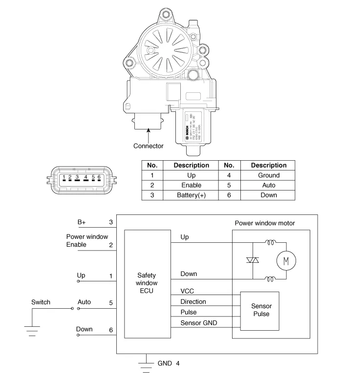
Power Window Motor
[Safety window]
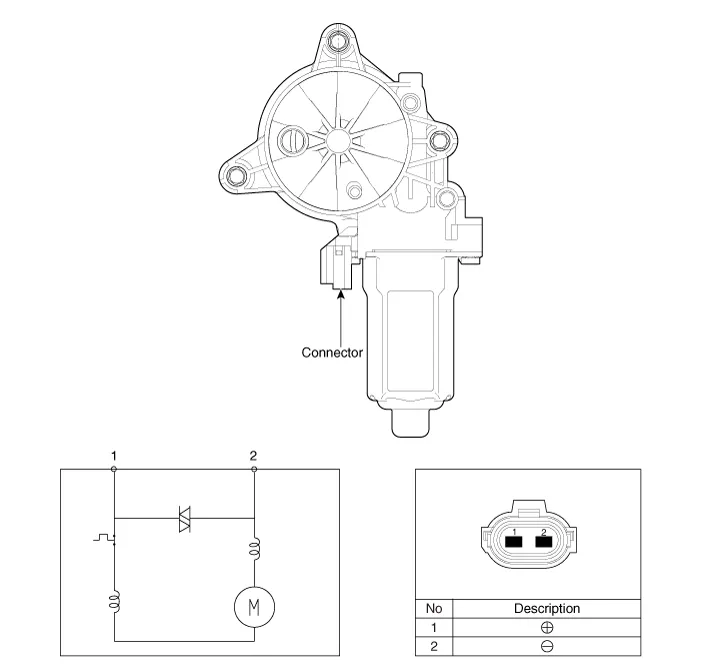
[General Window]
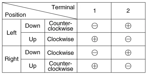
1.Disconnect the negative (-) battery terminal.
2.Remove the front door trim.(Refer to Body - "Front Door Trim")
3.Disconnect the connector (A) from the motor.
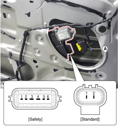
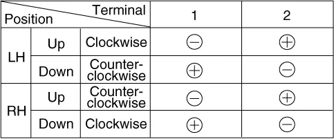
4.Connect the motor terminals directly to battery voltage (12V) and
check that the motor operates smoothly. Next, reverse the polarity and
check that the motor operates smoothly in the reverse direction. If the
operation is abnormal, replace the motor.
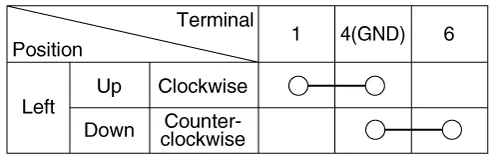
1.Disconnect the negative (-) battery terminal.
2.Remove the rear door trim.(Refer to Body - "Rear Door Trim")
3.Disconnect the connector (A) from the motor.
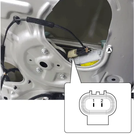
4.Connect the motor terminals directly to battery voltage (12V) and check that the motor operates smoothly. Next, reverse the polarity and check that the motor operates smoothly in the reverse direction. If the operation is abnormal, replace the motor.
Power Window Switch
Front+Rear, Door Lock + Drive Safety
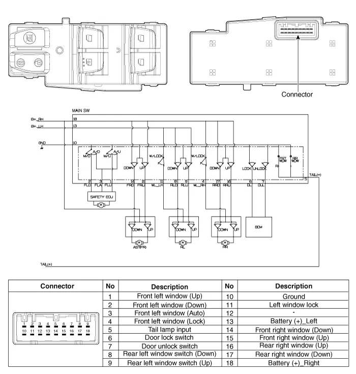
Front+Rear, Door Lock, Auto Down
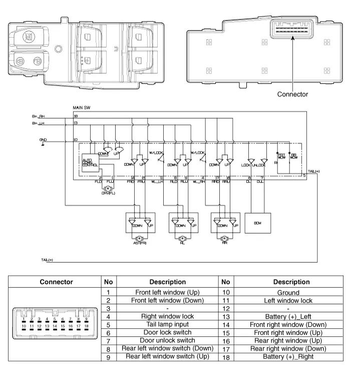
Front Only, Door Lock, Auto Dwon
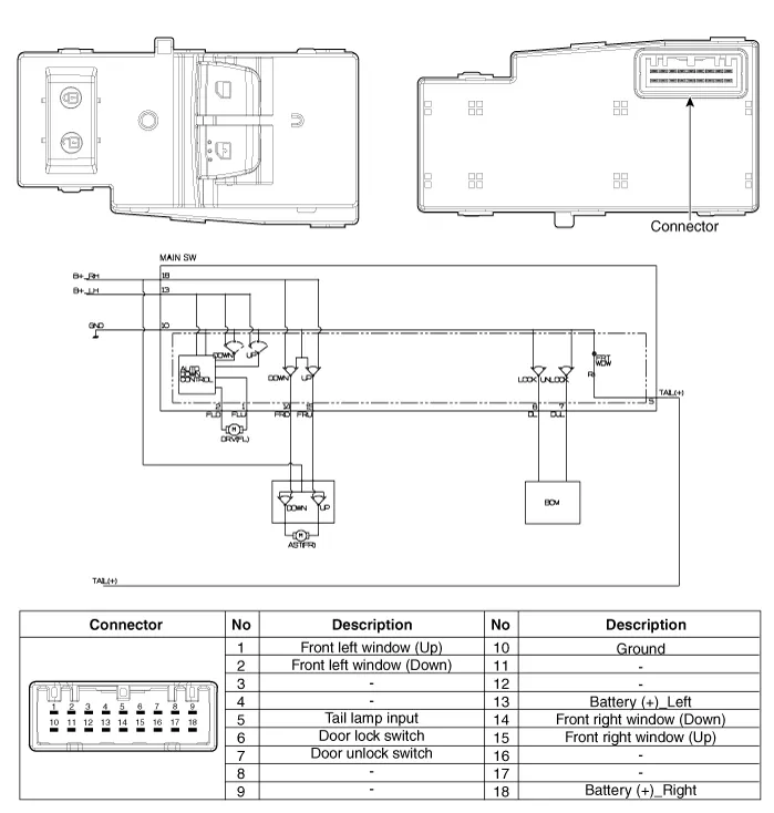
Front+Rear, Auto Down
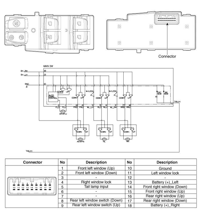
Front Only, Auto Dwon
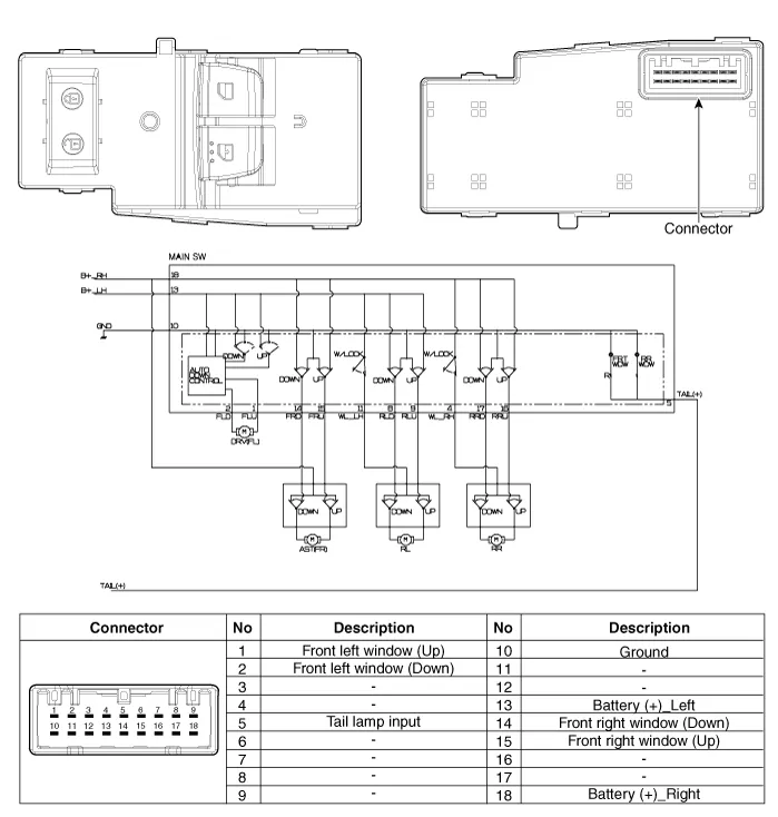
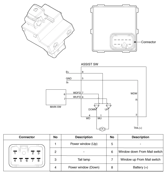
Assist Power Window Switch (Manual)
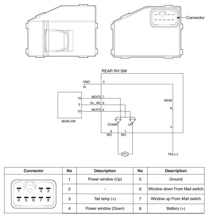
Rear Power Window Switch (Manual)
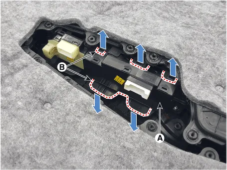
1.Disconnect the negative (-) battery terminal.
2.Remove the front door trim.(Refer to Body - "Front Door Trim")
3.Remove the power window switch assembly (A) by pulling out both ends of the switch holders (B).
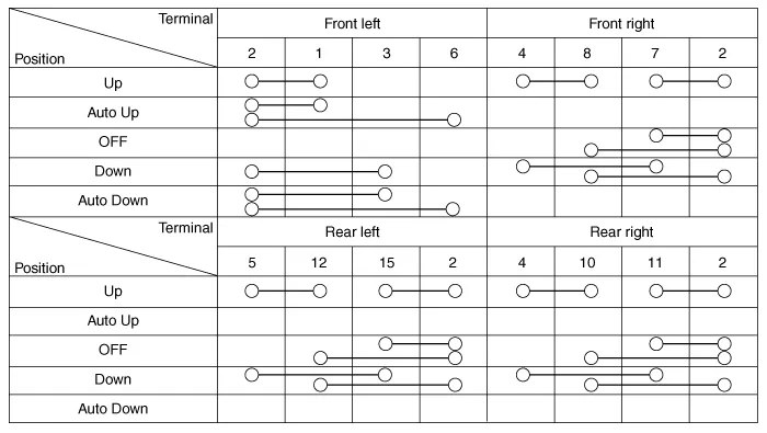
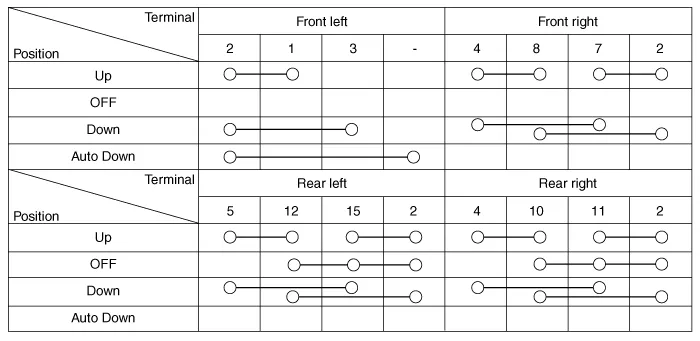
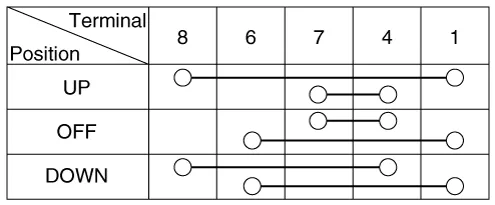
4.Check for continuity between the terminals in each switch position according to the table. If the continuity condition is not normal, replace the switch.
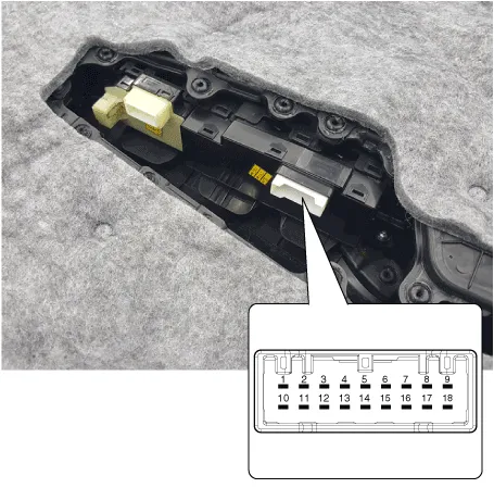
1.Disconnect the negative (-) battery terminal.
2.Remove the front door trim.(Refer to Body - "Front Door Trim")(Refer to Body - "Rear Door Trim")
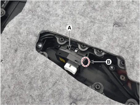
3.Remove the power window switch (A) after disengaging the mounting clips (B).
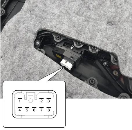
4.Check for continuity between the terminals in each switch position according to the table. If the continuity condition is not normal, replace the switch.
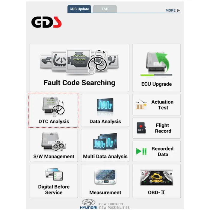
1.In the body electrical system, failure can be quickly diagnosed by using the vehicle diagnostic system (Diagnostic tool).The diagnostic system (Diagnostic tool) provides the following information.
(1)Fault Code Searching : Checking failure and code number (DTC)
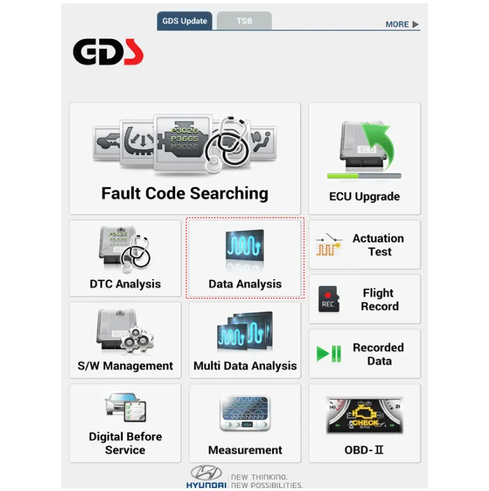
(2)Data Analysis : Checking the system input/output data state
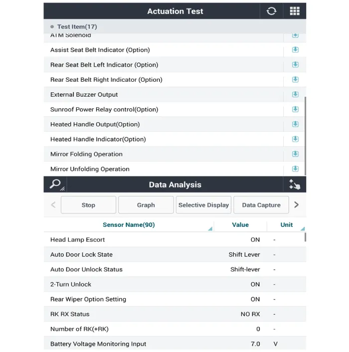
(3)Actuation test : Checking the system operation condition
(4)S/W Management : Controlling other features including system option setting and zero point adjustment
2.If diagnose the vehicle by Diagnostic tool, select "DTC Analysis" and "Vehicle".
3.Select the 'Data Analysis' and 'Car model'.
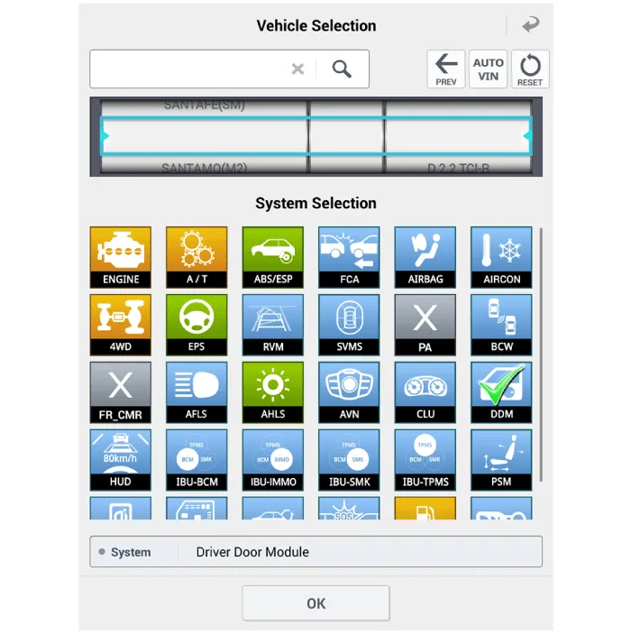
4.Select the 'DDM' to search the current state of the input/output data.
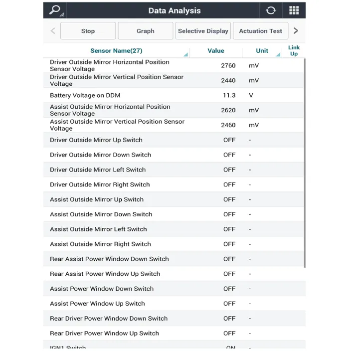
5.To forcibly actuate the input value of the module to be checked, select option 'Actuation Test'.


Other information:
Hyundai Accent (HC) (2017 - 2022) Service Manual: Owner maintenance
WARNING Performing maintenance work on a vehicle can be dangerous. If you lack sufficient knowledge and experience or the proper tools and equipment to do the work, have it done by an authorized HYUNDAI dealer. ALWAYS follow these precautions for performing maintenance work: Park your vehicle on level ground, move the shift lever into the P (Park, for intelligent variable transmission vehicle) position or neutral (for manual transmission vehicle), apply the parking brake, place the ignition switch in the LOCK/OFF position.
Contents
Categories
- Manuals Home
- Hyundai Accent Owners Manual
- Hyundai Accent Service Manual
- Questions & Answers
- Video Guides
- Useful Resources
- New on site
- Most important about car
- Privacy Policy

0.0105