Hyundai Accent (HC): Body Electrical System / Lighting System
Contents:
- Specifications
- Components and Components Location
- Head Lamps
- Room Lamp
- Overhead Console Lamp
- Turn Signal Lamp
- Hazard Lamp Switch
- Rheostat
- Fog Lamps
- License Lamps
- High Mounted Stop Lamp
- Rear Combination Lamp
- Troubleshooting
Specifications
| Items | Bulb Type | Bulb Wattage (W) | ||
| Front | Head lamp | General (Low/High) | H4 | 55 / 60 |
| Option (Low/High) Bi-function | 9005 HL+ | 60 | ||
| Turn signal lamp | PY21W | 21 | ||
| Position lamp | W5W | 5 | ||
| Fog lamp | H8 | 35 | ||
| Static bending light (SBL) | H7 | 55 | ||
| Type B (Daytime Running Lamp - DRL) | LED | LED | ||
| Rear | Rear combination lmap (General) | Turn signal lamp | PY21W | 21 |
| Stop / Tail lamp | P21/ 5W | 21/ 5 | ||
| Tail lamp | W5W | 5 | ||
| Back up lamp | W16W | 16 | ||
| Rear combination lmap (Option) | Inside Tail/stop lamp | LED | LED | |
| Out side Tail/stop lamp | LED | LED | ||
| Turn signal lamp | PY21W | 21 | ||
| Back up lamp | W16W | 16 | ||
| High mounted stop lamp | W16W | 16 | ||
| Rear Fog lamp | P21W | 21 | ||
| License plate lamp | W5W | 5 | ||
| Overhead console lamp | FESTOON | 10 | ||
| Room lamp | FESTOON | 8 | ||
| Vanity lamp | FESTOON | 5 | ||
Components and Components Location
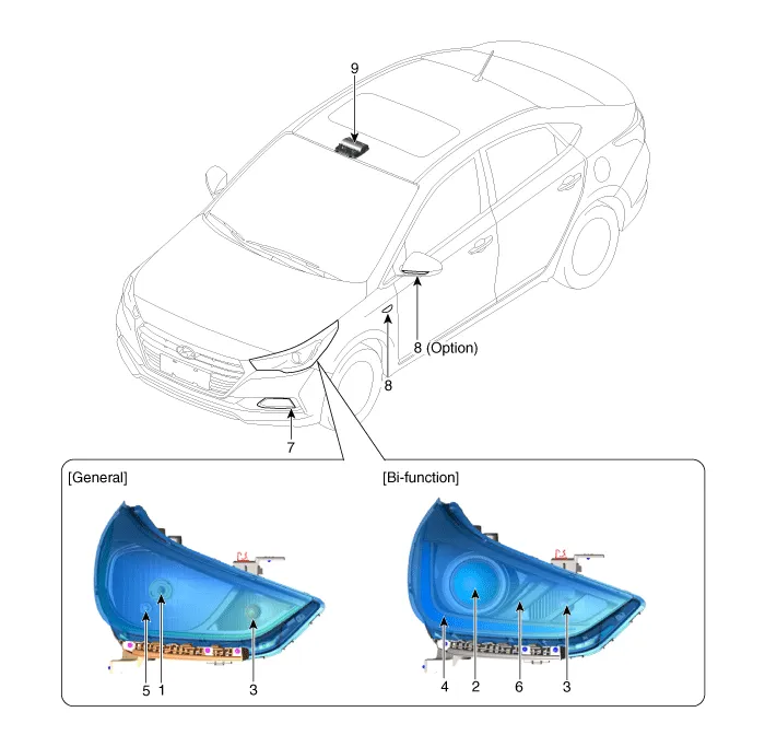
1. Head lamp (Low/High)
2. Head lamp (Low/High BI _Function)
3. Turn signal lamp
4. Daytime running light (DRL) & Position lamp
5. Position lamp
6. Static bending light (SBL)
7. Fog lamp
8. Side repeater lamp
9. Overhead console lamp
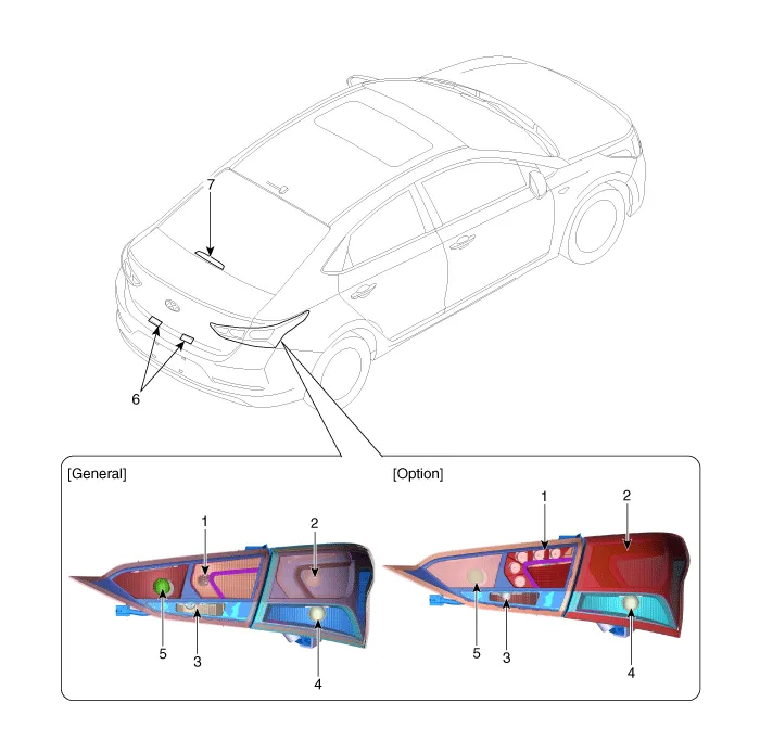
1. Tail lamp
2. Stop/Tail lamp
3. Back up lamp
4. Turn singal lamp
5. Rear fog lamp
6. License plate lamp
7. High mounting stop lamp
Head Lamps
[General]
1. Turnsignal lmap bulb
2. High / Low Beam bulb
3. Position lamp
4. Dust cap
[Bi-Function]
1. Static bending light bulb
2. Turnsignal lamp bulb
3. High / Low Beam bulb
4. Dust cap
1.BI-FUNCTION
(1)Definition
– A headlamp with integrated functions of high and low beam.
– The light is controlled by rotating the shield inserted to the lens (A solenoid is adopted)
(2)Structure and mechanism
– Case of working as a low beam:The light illuminates to the restricted area of low beam by blocking the light with the stopped shield.
– Case of working as a high beam:The light is not blocked by the open shield and the light illuminates to the area of high beam.
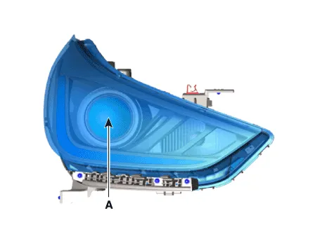
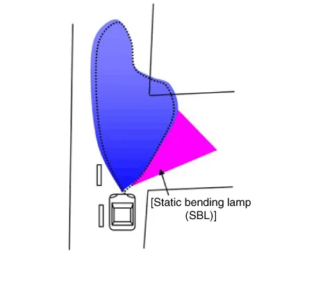
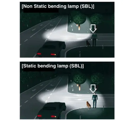
2.Static Bending Light (SBL)
(1)Definition
– Acquires visibility in corner when turning at night.
– L/R Static Bending Lamp is turned ON/OFF based on the vehicle speed and steering wheel angle.

(2)Vehicle Input Factors : Vehicle speed, steering wheel angle


1.Disconnect the negative (-) battery terminal.
2.Remove the front bumper cover.(Refer to Body - "Front Bumper Cover")
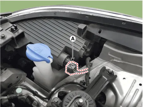
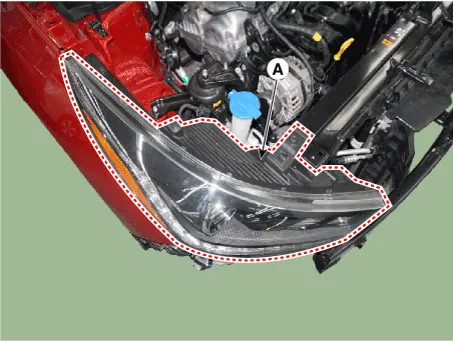
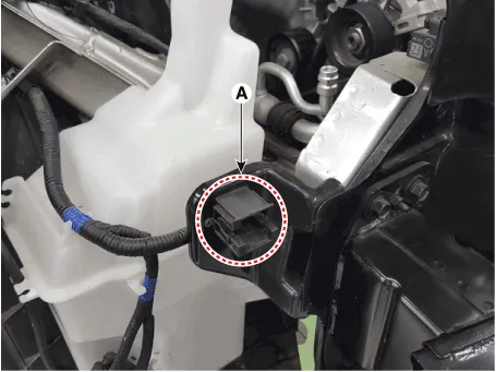
3.Disconnect the lamp connector (A) from the head lamp assembly.
4.Remove the head lamp assembly (A) after loosening the mounting bolts.

1.Install the head lamp bulbs.
2.Reassemble the head lamp bulb covers.
3.Reassemble the head lamp assembly after connecting the lamp connector.
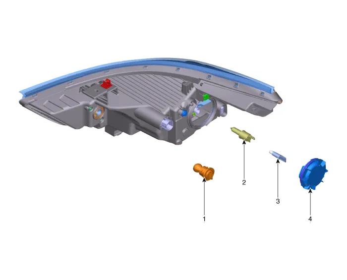
General Head Lamp Bulb
1.Turn the head lamp switch off.
2.Disconnect the power connector from the lamp.
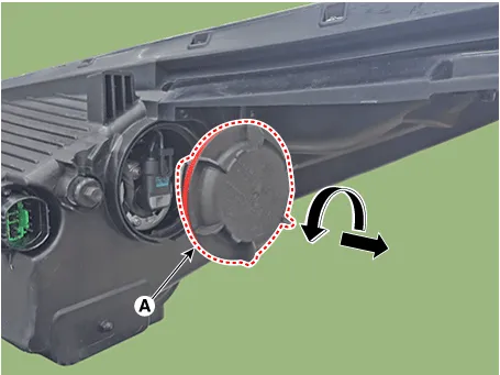
3.Remove the dust cap (A).
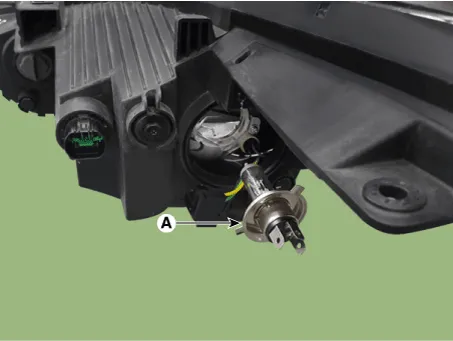
4.Disconnect the connector (A) from the bulb.
5.Disengaging the retaining clip (A).

6.Remove the heam lamp High/Low beam bulb (A).
7.Installation is the reverse of removal.
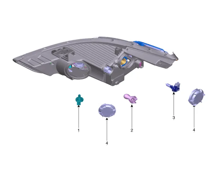
Bi-Function Head Lamp Bulb
1.Turn the head lamp switch off.
2.Disconnect the power connector from the lamp.
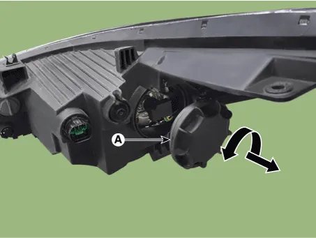
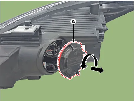
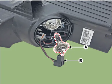
3.Remove the dust cap (A) after turning the dust cap counterclockwise.
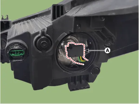
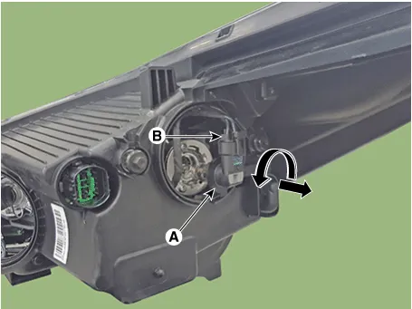
4.Replace the head lamp bulb (A) after turning the bulb socket counterclockwise and disconnecting the connector(B).
5.Installation is the reverse of removal.
Static bending light (SBL)
1.Turn the head lamp switch off.
2.Disconnect the power connector from the lamp.
3.Remove the dust cap (A) after turning the dust cap counterclockwise.
4.Remove the static bending lignt bulb (A) after disconnecting the connector (B).
5.Installation is the reverse of removal.
Turn Signal Lamp
1.Turn the head lamp switch off.
2.Remove the bulb socket (A) and bulb (B) from the lamp assembly.

1.Inflate the tires to the specified pressure and remove any loads from the vehicle except the driver, spare tire, and tools.
2.The vehicle should be placed on a flat floor.
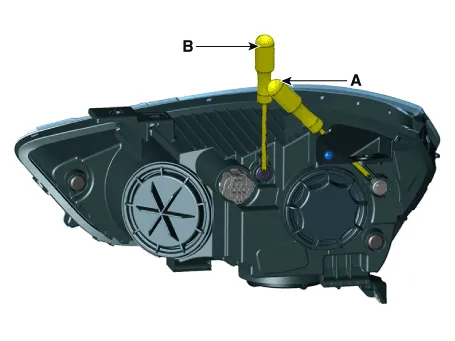
3.Draw vertical lines (Vertical lines passing through respective head lamp centers) and a horizontal line (Horizontal line passing through center of head lamps) on the screen.
4.With the head lamp and battery in normal condition, aim the head lamps so the brightest portion falls on the horizontal and vertical lines.A : HorizontalB : Vertical
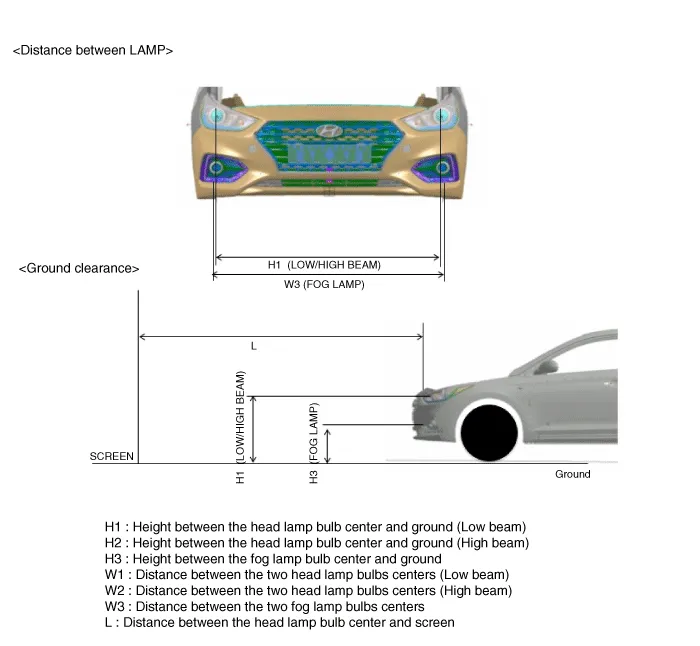
| Specifications | Vehicle condition | H1 | H3 | W1 | W3 | L |
| Standard | Without driver | 27.4 (697) | 16.2 (412) | 54.9 (1394) | 55.3 (1405) | Refer to aiming condition |
| With driver | 27.1 (689) | 15.9 (404) | 54.9 (1394) | |||
| Option | Without driver | 27.5 (705) | - | 55.0 (1397) | - | |
| With driver | 27.4 (697) | 55.0 (1397) |
| Specifications | Vehicle condition | H1 | H3 | W1 | W3 | L |
| Standard | Without driver | 28.0 (712) | 16.8 (427) | 54.9 (1394) | 55.3 (1405) | Refer to aiming condition |
| With driver | 27.7 (704) | 16.4 (419) | 54.9 (1394) | |||
| Option | Without driver | 28.3 (720) | - | 55.0 (1397) | - | |
| With driver | 28.0 (712) | 55.0 (1397) |
| Specifications | Vehicle condition | H1 | H3 | W1 | W3 | L |
| Standard | Without driver | 27.0 (687) | 15.8 (402) | 54.9 (1394) | 55.3 (1405) | Refer to aiming condition |
| With driver | 26.7 (679) | 15.5 (394) | 54.9 (1394) | |||
| Option | Without driver | 27.3 (695) | - | 55.0 (1397) | - | |
| With driver | 27.0 (687) | 55.0 (1397) |
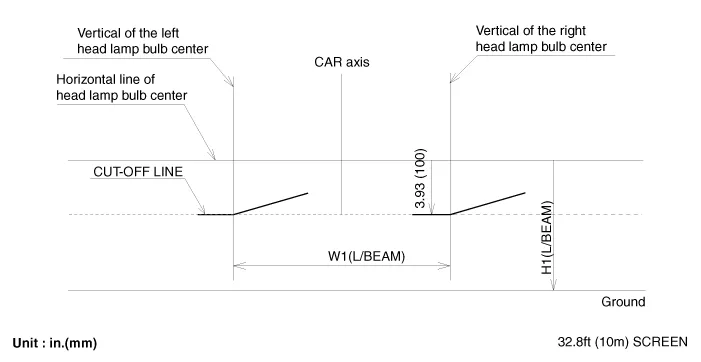
1.Head Lamp (Low beam)
– Turn the low beam on without driver aboard.
– The cut-off line should be projected in the cut-off line shown in the picture.
– When aiming the low beam, vertical aiming shuld be adjusted after adjusting the horizontal aiming.
– If head lamp leveling device is equipped, adjust the head lamp leveling device switch with 0 positions.
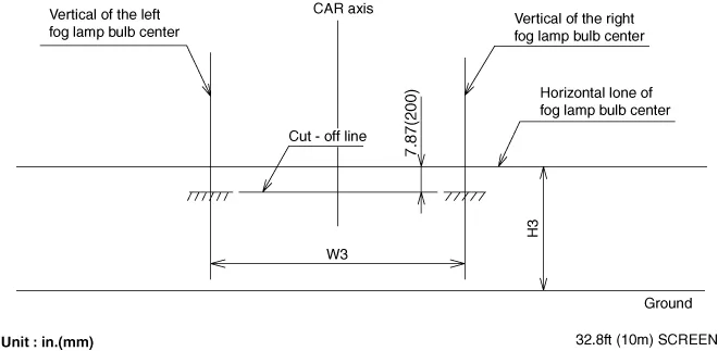
2.Turn the front fog lamp on without the driver aboard.The cut-off line should be projected in the allowable range (shaded region)
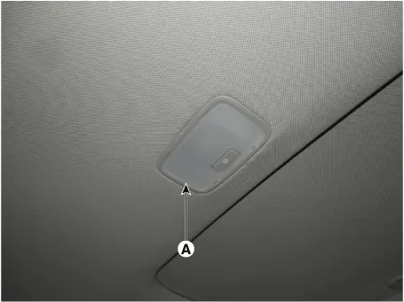
Room Lamp
1.Disconnect the negative (-) battery terminal.
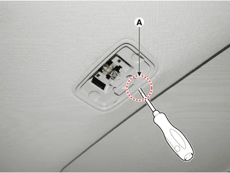
2.Using a screwdriver or remover, Separate the room lamp lens (A) from the room lamp.

• Put on gloves to prevent hand injuries.
• When removing with a flat-tip screwdriver or remover, wrap protective tape around the tools to prevent damage to components.
3.If it is necessary to replace the bulb, remove the bulb (A) after disengaging the room lamp lens.
4.Disengage the room lamp (B) after loosening the mounting screws.
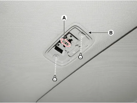

• When removing the room lamp, be careful of the direction in which the tool is inserted.
• Use caution when inserting the tool in the opposite direction, as the room lamp is damaged.
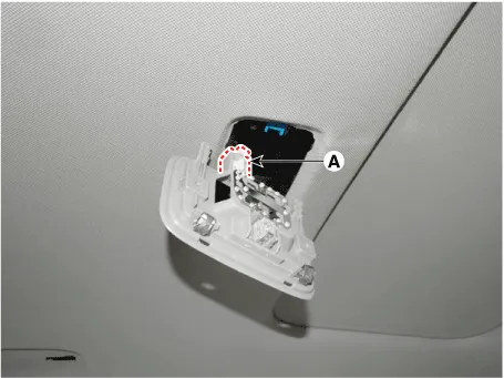
5.Remove the room lamp assembly after disconnect the room lamp connector.
1.Install the room lamp after connect the connector.
2.Install the room lamp lens
3.Connect the negative (-) battery terminal.
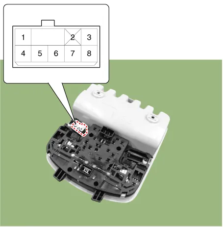
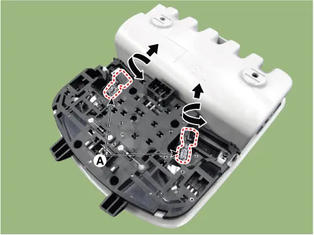
Overhead Console Lamp
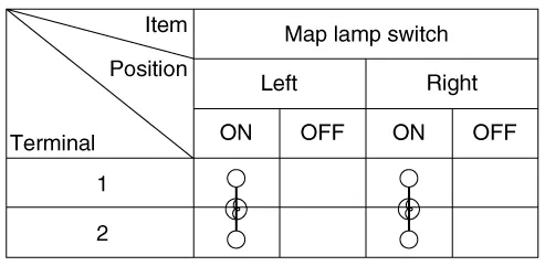
1.Remove the overhead console lamp assembly then check for continuity between terminals. If the continuity is not as specified, replace the map lamp switch.
1.Disconnect the negative (-) battery terminal.
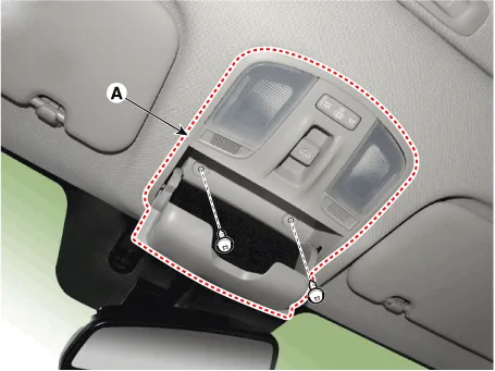
2.Remove the mounting screws (2EA).And then remove the overhead console (A).
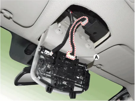
3.Remove the overhead console after disconnect the connector (A).
4.Remove the overhead console lamp (B) by turning the socket.
1.Install the overhead console lamp after connecting the connector.
2.Install the lens after tightening 2 screws.
Turn Signal Lamp
Door Mirror Side Repeater Lamp
1.Disconnect the negative (-) battery terminal.
2.Remove the door mirror side repeater lamp.(Refer to Power Door Mirrors - "Power Door Mirror Actuator")
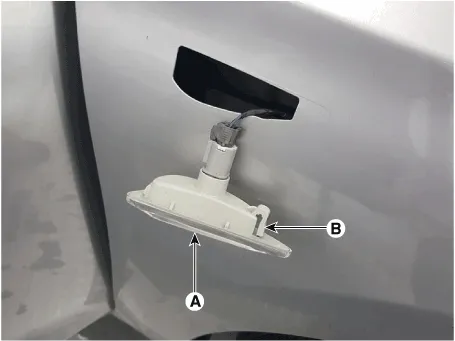
Fender Side Turn Signal Lamp
1.Disconnect the negative (-) battery terminal.
2.Remove the fender side turn signal lamp (A) after disengaging the mounting clip (B) and disconnecting the connector.
Door Mirror Side Repeater Lamp
1.Install the door mirror turn signal lamp.
2.Install the door mirror cover and housing.
3.Install the door mirror.
4.Connect the negative (-) battery terminal.
Fender Side Turn Signal Lamp
1.Install the fender side turn signal lamp and connecting the connector.
2.Connect the negative (-) battery terminal.
Hazard Lamp Switch
1.The Interior Junction Block can be diagnosed by using the GDS. The Interior Junction Block communicates with the GDS which then displays inputs and outputs along with codes.It will be able to diagnose defects of hazard lamp switch with GDS quickly. GDS can operates actuator forcefully, input/output value monitoring and self diagnosis.
2.To diagnose the Interior Junction Block function, select the vehicle model, BCM and Interior Junction Block.
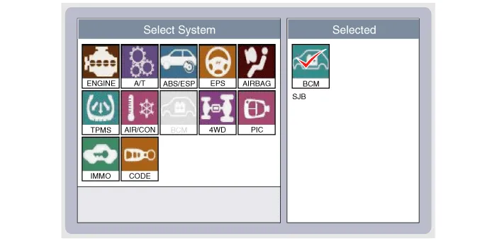
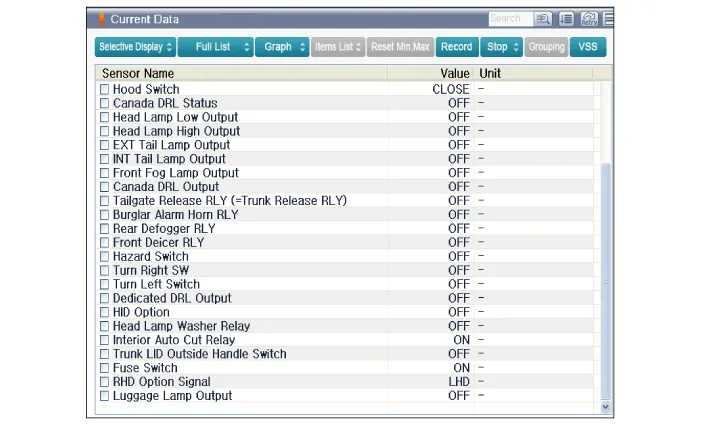
3.To consult the present input/out value of Interior Junction Block, "Current DATA". It provides information of Interior Junction Block input/output conditions.
1.Disconnect the negative (-) battery terminal.
2.Remove the A/C & heater controller unit.(Refer to Heating, Ventilation and Air Conditioning - "Controller")
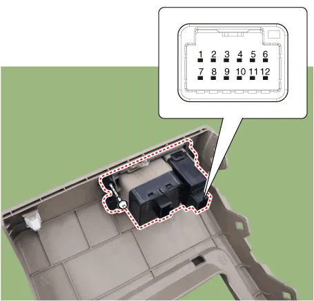
Rheostat
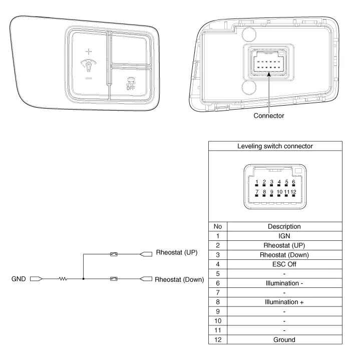
1.Disconnect the negative (-) battery terminal.
2.Remove the crash pad side cover.
3.Remove the crash pad lower panel (A).(Refer to Body - "Crash Pad Lower Panel")
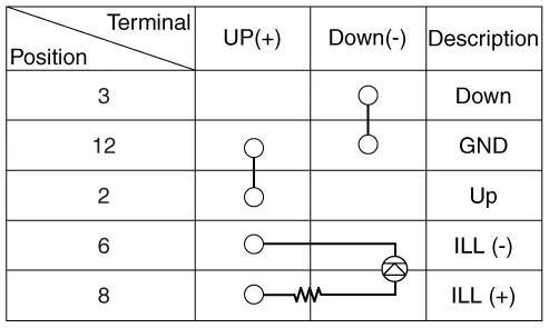
4.Check for intensity of new rheostat switch. If the light intensity of the lamps changes smoothly without any flickering when the rheostat is turned, it can be assumed that the rheostat is normal.
Fog Lamps
1.With the fog lamp switch in each position, make sure that continuity exists between the terminals below. If continuity is not as specified, replace the multifunction switch.
| Switch position | Switch terminal | Resistance (Ω, ±3.5%) |
| OFF | 9-10 | ∞ |
| Front foglamp | 910 |
1.Disconnect the negative (-) battery terminal.
2.Remove the front bumper.(Refer to Body - "Front Bumper Cover")
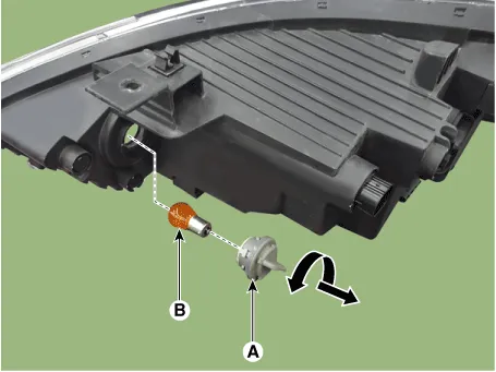
3.Remove the front fog lamp assembly (A) after loosening the mounting screws (4EA).
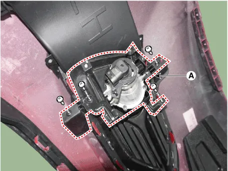
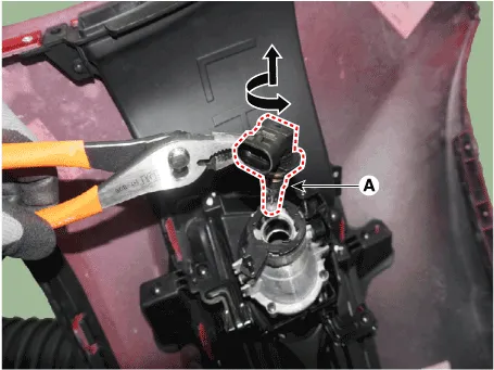
4.Remove the front fog lamp (A) by turning in the counter clock-wise direction after disconnecting the connector.
1.Install the front fog lamp bulb.
2.Connect the front fog lamp connector.
3.Install the front bumper.
License Lamps
1.Disconnect the negative (-) battery terminal.
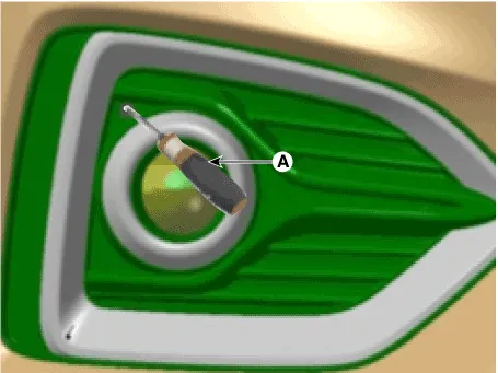
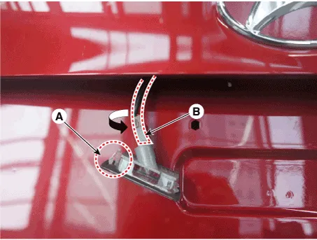
2.Remove the license lamp assembly after pushing the fixing clip (A).
3.Replace the bulb after turning the bulb socket (B) counterclockwise.
1.Install the bulb.
2.Install the license lamp lens.
High Mounted Stop Lamp
1.Disconnect the negative (-) battery terminal.
2.Remove the rear package tray trim.(Refer to Body - "Rear Package Tray Trim")
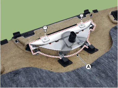
3.Remove the high mounted stop lamp (A) after loosening the mounting screws.
1.Disconnect the negative (-) battery terminal.
2.Open the trunk lid.
3.Remove the lamp bulb (A) by turning in the counter clock-wise direction.
1.Install the high mounted stop lamp.
2.Install the rear package tray trim.
3.Connect the negative (-) battery terminal.
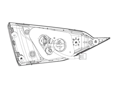
Rear Combination Lamp
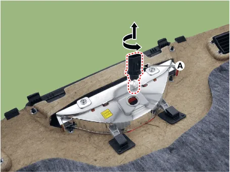
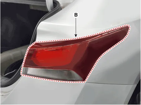
Outside Combination Lamp
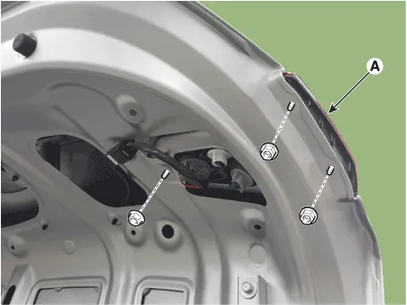
1.Disconnect the negative (-) battery terminal.
2.Remove the outside combination lamp (B) after disconnecting the lamp connector (A) and loosening the mounting nut.
3.Replace the tail lamp bulb (A) and turnsignal lamp bulb (B) after turning the bulb socket counterclockwise.
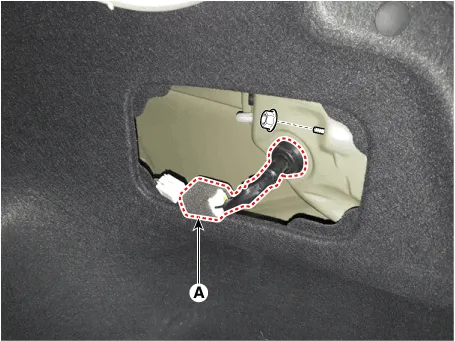
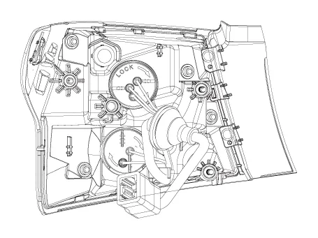
Inside Combination Lamp
1.Disconnect the negative (-) battery terminal.
2.Remove the inside combination lamp (A) after loosening the mounting nuts and disconnecting the connector.
3.If it is necessary to replace the bulb, remove the bulb after removing the trunk service cover.
1.Install the trunk combination lamp assembly after assembling the bulb.
2.Install the lamp cover to the trunk after connecting the lamp connector.
3.Install the rear combination lamp assembly after assembling the bulbs and connecting the lamp connector.
Troubleshooting
| Symptom | Possible Cause | Remedy |
| One lamp does not light (all exterior) | Bulb burned out | Replace bulb |
| Socket, wiring or ground faulty | Repair if necessary | |
| Head lamps do not light | Bulb burned out | Replace bulb |
| Ignition fuse (LOW:10A, HIGH:20A) blown | Check for short and replace fuse | |
| Head lamp fuse (15A) blown | Check for short and replace fuse | |
| Head lamp relay faulty | Check relay | |
| Lighting switch faulty | Check switch | |
| Wiring or ground faulty | Repair if necessary | |
| Tail lamps and license plate lamps do not light | Bulb burned out | Replace bulb |
| Tail lamp fuse (10A) blown | Check for short and replace fuse | |
| Tail lamp relay faulty | Check relay | |
| Lighting switch faulty | Check switch | |
| Wiring or ground faulty | Repair if necessary | |
| Stop lamps do not light | Bulb burned out | Replace bulb |
| Stop lamp fuse (15A) blown | Check for short and replace fuse | |
| Stop lamp switch faulty | Adjust or replace switch | |
| Wiring or ground faulty | Repair if necessary | |
| Stop lamps do not turn off | Stop lamp switch faulty | Repair or replace switch |
| Instrument lamps do not light (Tail lamps light) | Rheostat faulty | Check rheostat |
| Wiring or ground faulty | Repair if necessary | |
| Turn signal lamp does not flash on one side | Bulb burned out | Replace bulb |
| Turn signal switch faulty | Check switch | |
| Wiring or ground faulty | Repair if necessary | |
| Turn signal lamps do not light | Bulb burned out | Replace bulb |
| Turn signal lamp fuse (10A) blown | Check for short and replace fuse | |
| Flasher unit faulty | Check flasher unit | |
| Turn signal switch faulty | Check switch | |
| Wiring or ground faulty | Repair if necessary | |
| Hazard warning lamps do not light | Bulb burned out | Replace bulb |
| Hazard warning lamp fuse (15A) blown | Check for short and replace fuse | |
| Flasher unit faulty | Check flasher unit | |
| Hazard switch faulty | Check switch | |
| Wiring or ground faulty | Repair if necessary | |
| Flasher rate too slow or too fast | Lamps' wattages are smaller or larger than specified | Replace lamps |
| Flasher unit faulty | Check flasher unit | |
| Back up lamps do not light | Bulb burned out | Replace bulb |
| Back up lamp fuse (10A) blown | Check for short and replace fuse | |
| Back up lamp switch (M/T) faulty | Check switch | |
| Transaxle range switch (A/T) faulty | Check switch | |
| Wiring or ground faulty | Repair if necessary | |
| Room lamp does not light | Bulb burned out | Replace bulb |
| Room lamp fuse (10A) blown | Check for short and replace fuse | |
| Room lamp switch faulty | Check switch | |
| Wiring or ground faulty | Repair if necessary | |
| Front fog lamps do not light | Bulb burned out | Replace bulb |
| Front fog lamp fuse (15A) blown | Check for short and replace fuse | |
| Front fog lamp relay faulty | Check relay | |
| Front fog lamp switch faulty | Check switch | |
| Wiring or ground faulty | Repair if necessary | |
| Wiring or ground faulty | Repair if necessary | |
| Map lamp does not light | Bulb burned out | Replace bulb |
| Room lamp fuse (10A) blown | Check for short and replace fuse | |
| Map lamp switch faulty | Check switch | |
| Wiring or ground faulty | Repair if necessary | |
| Trunk room lamp does not light | Bulb burned out | Replace bulb |
| Room lamp fuse (10A) blown | Check for short and replace fuse | |
| Trunk room lamp switch faulty | Check switch | |
| Wiring or ground faulty | Repair if necessary |


Other information:
Hyundai Accent (HC) (2017 - 2022) Service Manual: Exterior Care
NOTICE If you park your Hyundai Accent near a stainless steel sign or glass facade building, the vehicle's exterior plastic parts such as a bumper, spoiler, garnish, lamp or outside rearview mirror might be damaged due to sunlight reflected from the sign or building. To prevent damage of the exterior plastic parts, you should avoid parking in areas where light may be reflected or use a car cover.Hyundai Accent (HC) (2017 - 2022) Service Manual: Manual Heating and Air Conditioning
You can also operate the heating and cooling system manually by pressing buttons other than AUTO. In this mode, the system follows your selections in sequence, while functions you do not adjust may still be managed automatically. When pressing any button except the AUTO button while using automatic operation, the functions not selected will be controlled automatically.
Contents
- Specifications
- Components and Components Location
- Head Lamps
- Room Lamp
- Overhead Console Lamp
- Turn Signal Lamp
- Hazard Lamp Switch
- Rheostat
- Fog Lamps
- License Lamps
- High Mounted Stop Lamp
- Rear Combination Lamp
- Troubleshooting
Categories
- Manuals Home
- Hyundai Accent Owners Manual
- Hyundai Accent Service Manual
- Questions & Answers
- Video Guides
- Useful Resources
- New on site
- Most important about car
- Privacy Policy

0.0081