Hyundai Accent (HC): Manual Transaxle System (M6CF1) / Manual Transaxle System
Contents:
Manual Transaxle Fluid
1.Check & Change intervals
| Check & Replenishment | Change | Capacity | Oil specification | |||||||||
| Normal use | Severe Use | |||||||||||
| 60,000 km / 4 years (40,000 miles / 4years) | No service required | 120,000 km (80,000 miles) | 1.5 - 1.6 L (0.40 -0.42 U.S.gal., 1.58 - 1.69 U.S.qt., 1.32- 1.40 lmp qt.) | API Service GL-4, SAE 70W
| ||||||||
![]()
• Driving in dusty, rough roads
• Driving in areas using salt or other corrosive materials or in very cold weather
• Driving in sandy areas
• Driving in mountainous areas
• Towing a trailer
• Driving for patrol car, taxi, commercial car or vehicle towing
• Driving over 170 Km
1.Uplift the vehicle with lift.
2.Remove the under cover.(Refer to Engine Mechanical System - "Engine Room Under Cover")
3.Loosen the oil filler plug (A).
![]()
4.Check the oil level.
![]()
• For the accuracy, inspect the oil level after the oil is completely drained.
• Loosen the drain plug and wait for over 10 minutes until the oil is drained enough.
• After the inspection, inject the oil through the filler plug hole according to the specification.
• Specified fluid :1.5 - 1.6 L (0.40 - 0.42 U.S.gal., 1.58 - 1.69 U.S. qt., 1.32 - 1.40 lmp qt.)
• While draining, some of the oil flows into the transmission part and the oil may be less than the specification by 0.1 - 0.15 L (0.03 - 0.04 U.S.gal., 0.10 - 0.16 U.S. qt., 0.09 - 0.13 lmp qt.) This is normal and additional oil injection is not required.
5.Install the filler plug with new gasket.
Tightening torque:58.9 - 78.5 N.m (6.0 - 8.0 kgf.m, 43.4 - 57.8 lb-ft)
6. Install the under cover.(Refer to Engine Mechanical System - "Engine Room Under Cover")
1.Uplift the vehicle with lift.
2.Remove the under cover.(Refer to Engine Mechanical System - "Engine Room Under Cover")
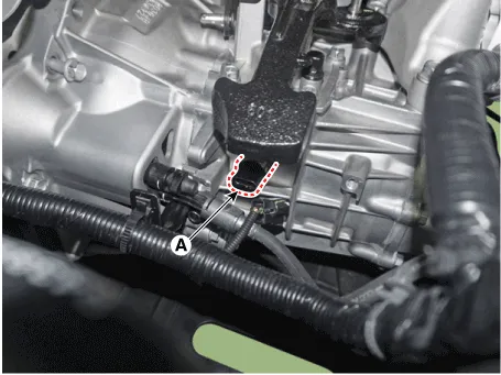
3.Drain the manual transaxle oil after loosening the drain plug (A) and then install the drain plug with new gasket.
Tightening torque :58.9 - 78.5 N.m (6.0 - 8.0 kgf.m, 43.4 - 57.8 lb-ft)
![]()
4. Loosen the oil filler plug (A).
![]()
5.Add new fluid through the filler plug hole.
Standard fluid : API Service GL-4, SAE 70WRecommnend oil:(SHELL : SPIRAX S6 GHME 70W, SK : HK MTF 70W, GS CALTEX : GS MTF HD 70W)Specified fluid : 1.5 - 1.6 L (0.40 - 0.42 U.S.gal., 1.58 - 1.69 U.S.qt., 1.32 - 1.40 lmp qt.)
6. Install the filler plug (A) with new gasket.
Tightening torque :58.9 - 78.5 N.m (6.0 - 8.0 kgf.m, 43.4 - 57.8 lb-ft)
![]()
![]()
• The existing oil filler plug gasket must be replaced with a new one. (Do not reuse it.)
7.Install the under cover.(Refer to Engine Mechanical System - "Engine Room Under Cover")
Manual Transaxle
![]()
1. Control shaft complete
2. Manual transaxle case
3. Clutch housing
4. Back-up lamp switch
5. Manual transaxle support bracket
6. Control cable bracket
1.Turn OFF ignition switch and disconnect the negative (-) battery cable.
2.Remove the air cleaner assembly and air duct.(Refer to Engine Mechanical System - "Air cleaner")
3.Remove the battery and battery tray.(Refer to Engine Electrical System - "Battery")
4.Remove the engine control module (ECM).(Refer to Engine Control System - "ECM")
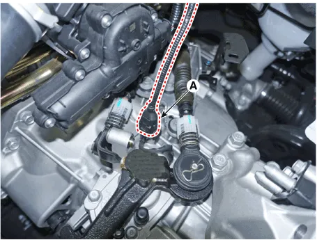
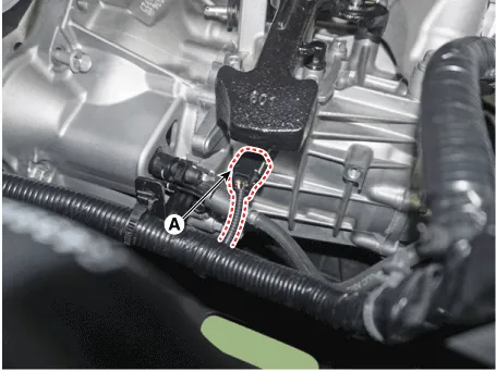
5.Disconnect the back-up lamp switch connector (A).
![]()
6.Remove the control cable bracket and control cable.
1)Remove the snap pin (A) and then separate the select cable (B) and shift cable (C).
2) Loosen the mounting bolts and then removing the control cable bracket (D).
Tightening torque : 14.7 - 21.6 N.m (1.5 - 2.2 kgf.m, 10.8 - 15.9 lb-ft)
![]()
![]()
7.Separate the ground line (A).
Tightening torque : 9.8 - 11.8 N.m (1.0 - 1.2 kgf.m, 7.2 - 8.7 lb-ft)
![]()
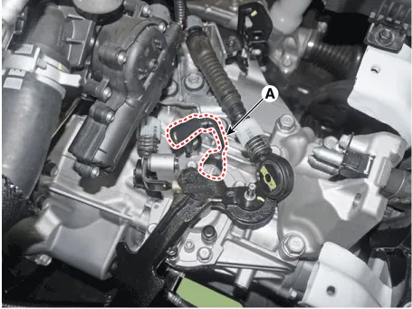
8.Disconnect the neutral switch connector (A).
![]()
9.Remove the clip (A) and then separate the concentric slave cylinder (B).
![]()
10.Loosen the starter mounting bolts (A) and the transaxle upper mounting bolts (B).
Tightening torque :(A) 49.0 - 63.7 N.m (5.0 - 6.5 kgf.m, 36.2 - 47.0 lb-ft)(B) 42.2 - 53.9 N.m (4.3 - 5.5 kgf.m, 31.1 - 39.8 lb-ft)
![]()
11.Assemble the engine support fixture(beam No.: 09200-38001 or 09200-3N000, supporter No.: 09200-2S000).
12.Using the engine support fixture (A), hold the engine and transaxle assembly safely.
![]()
13.Remove the dust cover (A).
![]()
14.Remove the transaxle support bracket mounting bolts (A).
Tightening torque :88.3 - 107.9 N.m (9.0 - 11.0 kgf.m, 65.1 - 79.6 lb-ft)
![]()
15.Remove the transaxle support bracket (A).
Tightening torque :58.9 - 78.5 N.m (6.0 - 8.0 kgf.m, 43.4 - 57.8 lb-ft)
![]()
16.Remove the under cover.(Refer to Engine Mechanical System - "Engine Room Under Cover")
17.Loosen the oil drain plug (A), and then drain the fluid.
Tightening torque :58.9 - 78.5 N.m (6.0 - 8.0 kgf.m, 43.4 - 57.8 lb-ft)
![]()
18.Remove the front drive shaft assembly.(Refer to Driveshaft and axle - "Front Drive Shaft")
19.Loosen the roll rod bracket bolts (A), (B) and then removing the roll rod bracket (C).
Tightening torque :(A) 49.0 - 63.7 N.m (5.0 - 6.5 kgf.m, 36.2 - 47.0 lb-ft)(B) 107.9 - 127.5 N.m (11.0 - 13.0 kgf.m, 79.6 - 94.1 lb-ft)
![]()
20.Remove the roll rod support bracket (A).
Tightening torque :49.0 - 68.6 N.m (5.0 - 7.0 kgf.m, 36.2 - 50.6 lb-ft)
![]()
21.Loosen the bolts and then removing the heat protect assembly (A).
![]()
22.Loosen the lower mounting bolts (A) and (B) of lower part of the transaxle, and the left side cover and remove the transaxle assembly by supporting it with a jack.
Tightening torque :(A) 42.2 - 48.1 N.m (4.3 - 4.9 kgf.m, 31.1 - 35.4 lb-ft)(B) 42.2 - 53.9 N.m (4.3 - 5.5 kgf.m, 31.1 - 39.8 lb-ft)
![]()
• Be careful not to damage other system or parts near by when removing the engine and transaxle assembly.
![]()
![]()
• If the oil seal on the transaxle case side is damaged and fluid is leaking, replace the oil seal with a new unit.
• When installing the new oil seal, use the specialized tool.
Oil seal installer both sides : 09431-26100
![]()
Handle both sides : 09231-H1100
![]()
1.To install, reverse the removal procedures.
2.Refil the manual transaxle fluid after Installing the manual transaxle.(Refer to Manual Transaxle System - "Manual Transaxle Fluid")
3.Perform bleeding air procedure in concentric slave cylinder after pouring the brake fluid. (Refer to Clutch System - "Concentric Slave Cylinder")
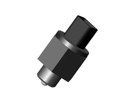
Back-up Lamp Switch
| Item | Specification |
| Current voltage | 12V |
| Working voltage | DC 10V - 15V |
| Operating force | Max. 3.0 kg |
| Voltage drop | Max. 0.24V |
| Working temperature | -30°C to 100°C [-30°F to 212°F] |
1.Turn OFF ignition switch and disconnect the negative (-) battery cable.
2.Remove the air cleaner assembly and air duct.(Refer to Engine Mechanical System - "Air Cleaner")
3.Remove the battery and battery tray.(Refer to Engine Electrical System - "Battery")
4.Remove the engine control module (ECM).(Refer to Engine Control System - "ECM")
5.Disconnect the back-up lamp switch connector (A).

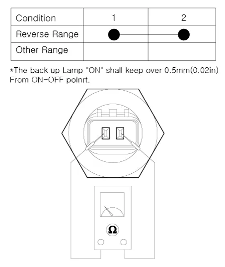
6.Check the continuity between no. 1 and 2 terminals of backup lamp switch. When the shift lever is in reverse, there should be continuity.
1.Turn OFF ignition switch and disconnect the negative (-) battery cable.
2.Remove the air cleaner assembly and air duct.(Refer to Engine Mechanical System - "Air Cleaner")
3.Remove the battery and battery tray.(Refer to Engine Electrical System - "Battery")
4.Remove the engine control module (ECM).(Refer to Engine Control System - "ECM")
5.Disconnect the back-up lamp switch connector (A).
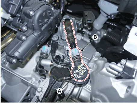
6.Remove the snap pin (A) and then separate the shift cable (B).
7.Replace a new one and install the back up lamp switch (A).
Tightening torque :39.2 - 58.8 N.m (4.0 - 6.0 kgf.m, 28.9 - 43.4 lb-ft)
Neutral Switch
• Components location : Manual transaxle case
• Operation principle :Neutral switch is installed in manual transaxle vehicle (ISG system or Diesel engines) and senses driver′s intension to shift gear.When vehicle starts to move after standing for a while and vehicle speed does not reach to 2Km/h, fuel quantity mapping value at neutral gear is adopted to vehicle.Moreover, this phenomenon is more serious when vehicle requires high power generation such as the situation when vehicle is on the slope.To cope with this problem, neutral gear switch which senses driver′s intension of starting to move is applied. And fuel injection quantity mapping value suitable for 1st gear is adopted immediately.
• Function : Fuel injection quantity mapping value suitable for 1st gear is adopted immediately when vehicle starts to move after standing for a while.
| Item | Specification |
| Current voltage | 12V |
| Working voltage | DC 10V - 15V |
| Operating force | Max. 3.0 kg |
| Voltage drop | Max. 0.24V |
| Working temperature | -30°C to 100°C [-30°F to 212°F] |
1.Turn OFF ignition switch and disconnect the negative (-) battery cable.
2.Remove the air cleaner assembly.(Refer to Engine Mechanical System - "Air Cleaner")
3.Disconnect the neutral switch connector (A).

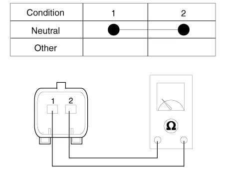
4.Check the continuity between no. 1 and 2 terminals of neutral position switch.When the shift lever is in neutral, there should be continuity.
1.Turn OFF ignition switch and disconnect the negative (-) battery cable.
2.Remove the air cleaner assembly.(Refer to Engine Mechanical System - "Air Cleaner")
3.Disconnect the neutral switch connector (A).
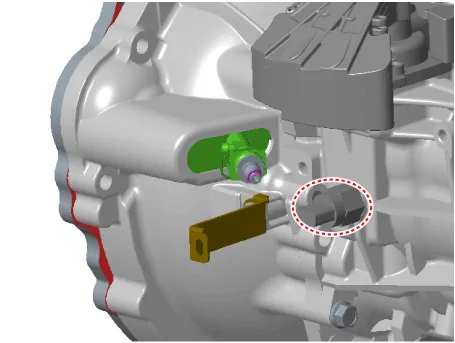
4.Replace the neutral position switch (A).
Tightening torque : 39.2 - 58.8 N.m (4.0 - 6.0 kgf.m, 28.9 - 43.4 lb-ft)


Other information:
Hyundai Accent (HC) (2017 - 2022) Service Manual: Explanation of scheduled maintenance items
Engine Oil and Filter The engine oil and filter should be changed at the intervals specified in the maintenance schedule. If the Hyundai Accent is being driven in severe conditions, more frequent oil and filter changes are required to protect the engine from accelerated wear and sludge buildup. Drive Belts Inspect all drive belts for evidence of cuts, cracks, excessive wear or oil saturation and replace if necessary.Hyundai Accent (HC) (2017 - 2022) Service Manual: Inside Rearview Mirror
Before you start driving, adjust the inside rearview mirror to center the view through the rear window. A correctly adjusted mirror in your Hyundai Accent helps you maintain safe awareness of traffic behind you without needing to change your seating position. WARNING Make sure your line of sight is not obstructed. Do not place objects in the rear seat, cargo area, or behind the rear headrests that could interfere with your vision through the rear window.
Contents
Categories
- Manuals Home
- Hyundai Accent Owners Manual
- Hyundai Accent Service Manual
- Questions & Answers
- Video Guides
- Useful Resources
- New on site
- Most important about car
- Privacy Policy

0.0076