Hyundai Accent (HC): Body Electrical System / Audio
Contents:
- Specifications
- Components and Components Location
- Audio Unit
- Speakers
- Antenna
- Audio Remote Control
- AUX(Auxiliary) Jack
- Mic
Specifications
Audio
| Item | Specification |
| Model | Audio display (MONO) |
| Power supply | DC 14.4V |
| Dark current | Max. 1mA (Head unit only) |
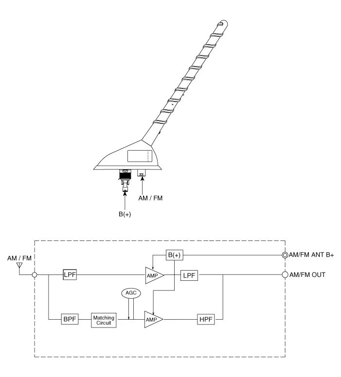
| Antenna | 80PF 75Ω |
| Tuning type | PLL SYNTHESIZED TUNING |
Components and Components Location
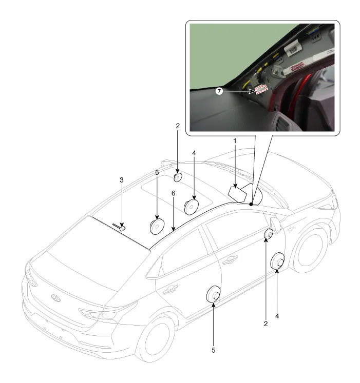
1. Audio unit
2. Tweeter speaker
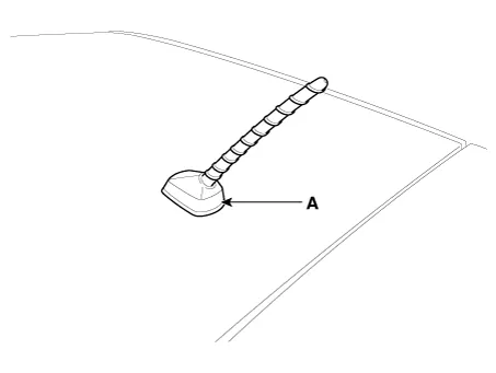
3. Roof antenna (Radio)
4. Front door speaker
5. Rear door speaker
6. Antenna feeder cable
7. Antenna cable connector
Audio Unit
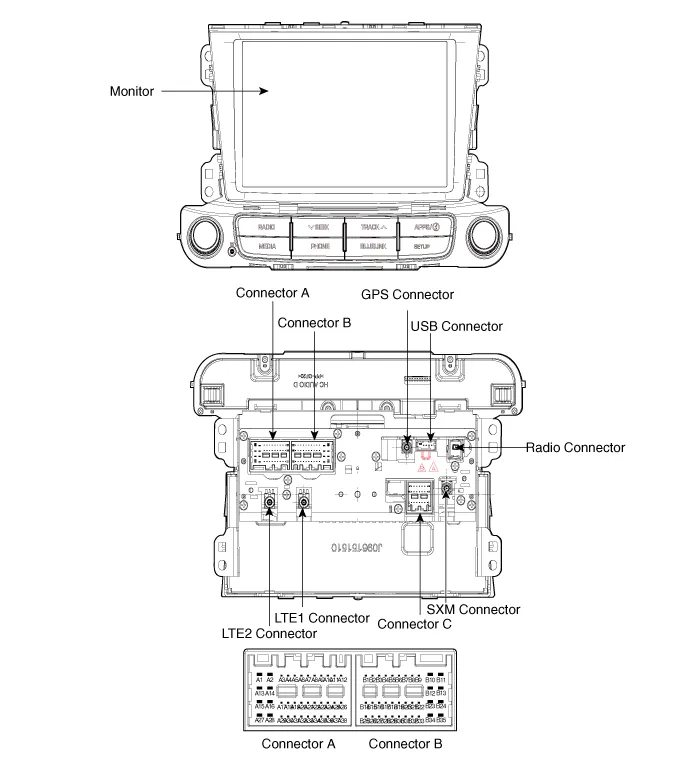
| No | Connector A | Connector B | Connector C |
| 1 | Left rear door speaker (+) | - | B_CAN (HI) |
| 2 | Left rear door speaker (-) | Mic signal (+) | C_CAN (HI)-bluelink only |
| 3 | - | - | - |
| 4 | - | - | - |
| 5 | - | Antenna power | - |
| 6 | Cameara power | Illumination (+) | - |
| 7 | Camera video | MM CAN (High) | - |
| 8 | - | - | B_CAN (Low) |
| 9 | - | Alt L out (-) | C_CAN (Low)-bluelink only |
| 10 | AUX Audio | Battery (+) | - |
| 11 | AUX Detect | Battery (+) | - |
| 12 | Steearing wheel remote controller | Ground | - |
| 13 | Left front door speaker (+) | Ground | - |
| 14 | Left front door speaker (-) | MIC ground | - |
| 15 | Right front door speaker (-) | Mic signal (-) | Airbag -bluelink only |
| 16 | Right front door speaker (+) | - | - |
| 17 | - | N- Positon | Bluelink switch-bluelink only |
| 18 | - | - | - |
| 19 | - | Illumination (-) | - |
| 20 | Camera power ground | MM CAN (Low) | - |
| 21 | Camera video ground | - | - |
| 22 | - | ACC | |
| 23 | - | - | |
| 24 | AUX Audio L | - | |
| 25 | AUX Audio ground | Reverse | |
| 26 | Steearing wheel remote controller ground | Door open | |
| 27 | Right rear door speaker (-) | Door unlock status | |
| 28 | Right rear door speaker (+) | Manual parking | |
| 29 | - | P Position | |
| 30 | - | AV tail | |
| 31 | - | Transmision detect | |
| 32 | - | - | |
| 33 | Camera shield ground | IGN 1 | |
| 34 | - | - | |
| 35 | - | - | |
| 36 | - | ||
| 37 | - | ||
| 38 | Speed |

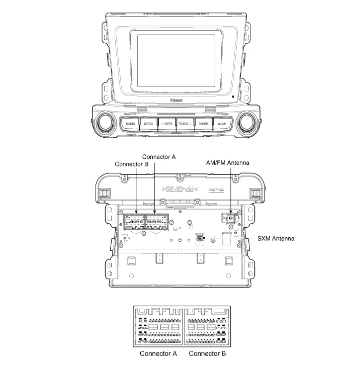
| No | Connector A | Connector B |
| 1 | Rear door speaker (Left +) | - |
| 2 | Rear door speaker (Left -) | Mic signal (+) |
| 3 | USB Ground | - |
| 4 | USB Data (High) | Detent |
| 5 | USB Data (Low) | Antenna power |
| 6 | USB Data (VCC) | Illumination (+) |
| 7 | CAMERA VIDEO | - |
| 8 | - | - |
| 9 | - | - |
| 10 | AUX Audio R | Battery (+) |
| 11 | AUX Detect | Battery (+) |
| 12 | Steering wheel remote control | Ground |
| 13 | Front door speaker (Left +) | Ground |
| 14 | Front door speaker (Left -) | - |
| 15 | Front door speaker (Righ -) | Mic signal (-) |
| 16 | Front door speaker (Righ +) | - |
| 17 | - | - |
| 18 | - | Vehicle speed |
| 19 | - | Illumination (-) |
| 20 | CAMERA POWER | - |
| 21 | CAMERA VIDEO GND | - |
| 22 | - | ACC |
| 23 | - | - |
| 24 | AUX Audio L | - |
| 25 | AUX Audio ground | REVERSE |
| 26 | Steering wheel remote control ground | Door open |
| 27 | Rear door speaker (Right -) | - |
| 28 | Rear door speaker (Right +) | Manual parking (MT) |
| 29 | - | P-Position (AT) |
| 30 | - | - |
| 31 | - | - |
| 32 | CAMERA POWER GND | IGN 1 |
| 33 | - | - |
| 34 | - | - |
| 35 | - | N Positon (M/T) |
| 36 | CAMERA DETENT | |
| 37 | Transmission detect (M/T) | |
| 38 | - |

1.Disconnect the negative (-) battery terminal.
2.Remove the center fascia panel.(Refer to Body - "Crash Pad")
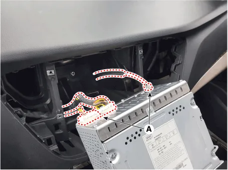
3.Seperate the audio head unit (A) from crash pad after loosening the screws (4EA).
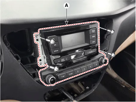
4.Remove the audio head unit after disconnecting the connectors and cable (A).
1.Connect the audio unit connectors and cable.
2.Install the audio head unit.
3.Install the center fescia panel.
4.Connect the negative (-) battery terminal.

1)Make sure the connector are connected in properly.
2)Check the audio system.
Speakers
1.Troubleshooting for Speaker
(1)Basic inspection of speakerInspect the sound from speaker after verifying that the speaker mounting screws is removed and the wiring connector is connected precisely to remove vibration transmitted from body trims and surrounding parts.
(2)Case Troubleshooting
| No | Case | Inspection/Remedy | ||||||||
| 1 | Trembling sound |
| ||||||||
| 2 | Noise |
|

3
Poor working
Inspection of the wiring connection between the battery and the speaker
1)Before replacing the speaker, inspect the wiring and connections in the speaker circuit.
2)Check the supplying power to the speaker and the resistance, and then inspect the sound quality.

3)If the speaker works poorly, replace it with new one.

– During dealing of speaker
– Dropping or rough handling of the speaker can cause damage.
– Be careful not to cover water and oil over the speaker.
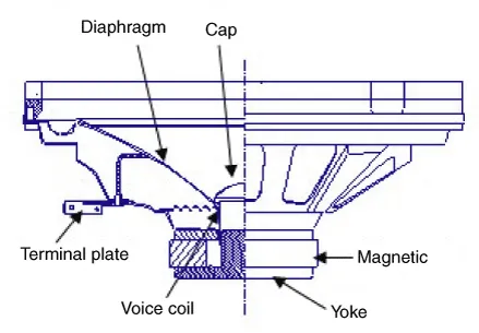
– Caution during dealing of speaker because the material of diaphragm is paper which is easy to be torn by impact and external force.
– When modifying audio system as customer pleases, this does electric damage to speaker.
– And, in this case the speakers are not covered by the manufacturer's warranty.
1.Remove the front door trim.(Refer to Body - "Front Door Trim")
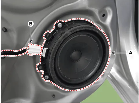
2.Remove the front speaker (A) after disconnecting the connector (B) and removing the mounting rivets (4EA).

1.Remove the rear door trim. (Refer to Body - "Rear Door Trim")
2.Remove the rear speaker (A) after disconnecting the connector (B) and removing the mounting rivets (4EA).
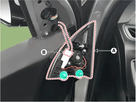
1.Using a screwdriver or remover, remove the front door quadrant inner cover (A).
2.Disconnect the tweeter speaker connector (B).
Front Speaker
1.Install the front speaker.
2.Install the front door trim.
Rear Speaker
1.Install the rear speaker.
2.Install the rear door trim.
Tweeter Speaker (Front)
1.Connect the connector.
2.Install the tweeter speaker and front door quadrant inner cover
Antenna
1.Remove the antenna jack from the audio unit and antenna.
2.Check for continuity between the center poles of antenna cable.
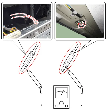
3.Check for continuity between the outer poles of antenna cable. There should be continuity.
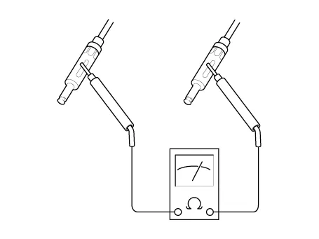
4.If there is no continuity, replace the antenna cable.
5.Check for continuity between the center pole (A) and outer pole (B) of antenna cable. There should be no continuity.
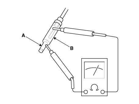
6.If there is continuity, replace the antenna cable.
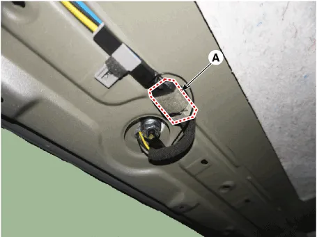
1.Remove the rear roof trim.(Refer to Body - "Roof Trim Assembly")
2.Disconnect the roof antenna connectors (A) from the roof antenna.
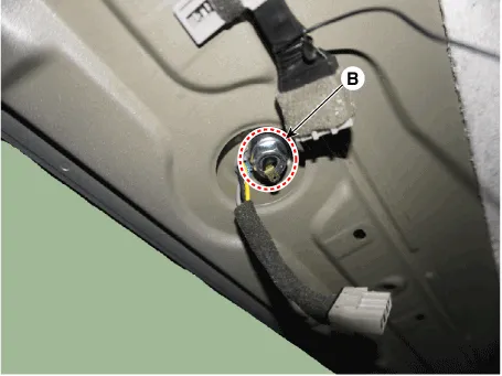
3.Remove the roof antenna (A) after removing a nut (B).
1.Connect the roof antenna connectors.
2.Install the rear roof trim.

– Make sure that the cables and connectors are plugged in properly.
– Check the audio system.
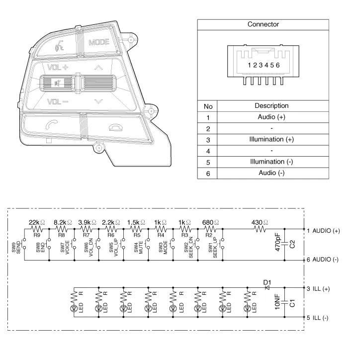
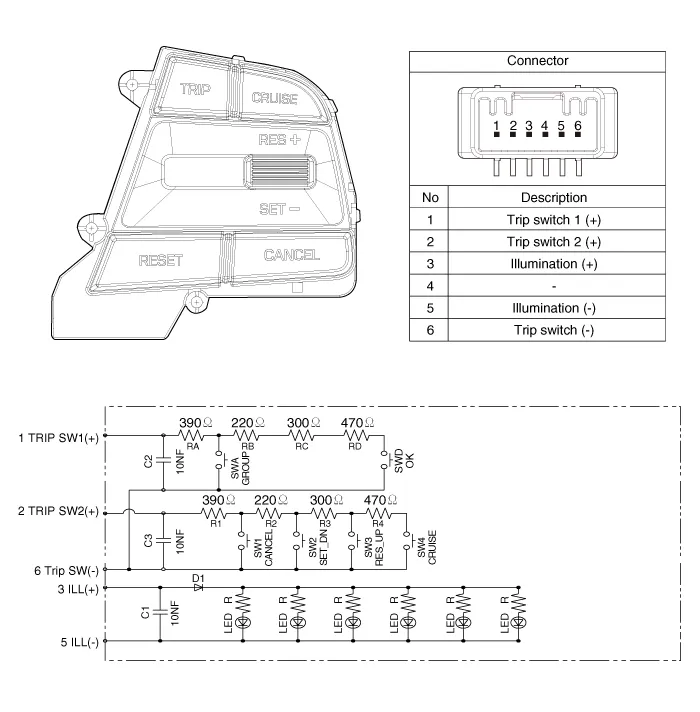
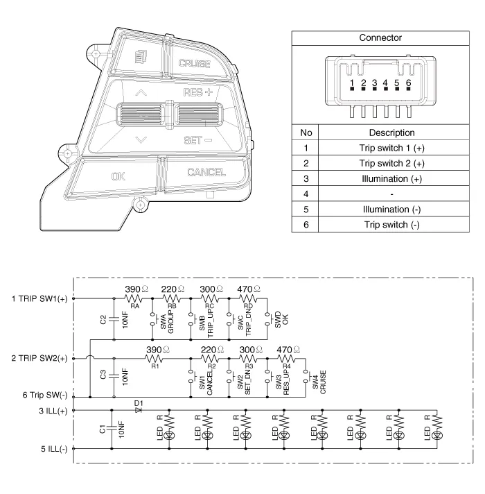
Audio Remote Control
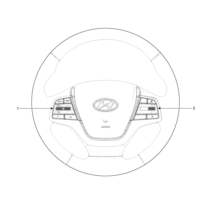
1. Remote control switch (LH)
2. Trip switch (RH)
Audio + Bluetooth + Voice
Trip (2 Button) + Cruise
Trip (4 Button) + Cruise
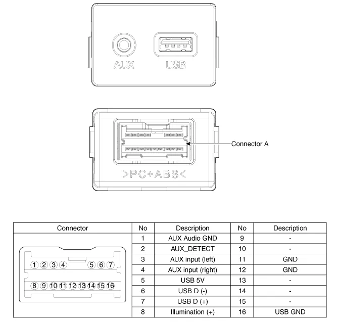
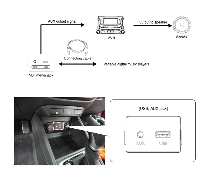
AUX(Auxiliary) Jack
1.Disconnect the negative (-) battery terminal.
2.Remove the console upper cover.(Refer to Body - "Floor Console Assembly")
3.Remove the floor console front bezel.(Refer to Body - "Floor Console Assembly")
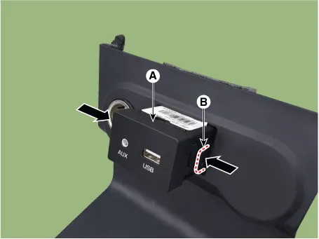
4.Remove the multimedia jack (A) after disengaging the hooks (B).
1.Install the multimedia jack.
2.Install the console front complete assembly.
3.Connect the negative (-) battery connector.
Mic
1.Disconnector the negative (-) battery terminal.
2.Remove the mic after disconnect the connector.
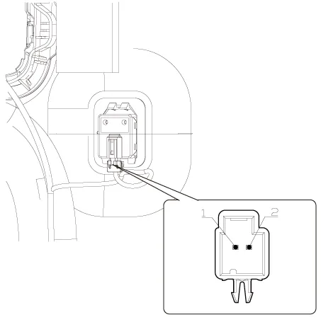
3.Check the continuity of between terminals.
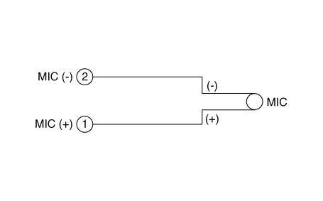


Other information:
Hyundai Accent (HC) (2017 - 2022) Service Manual: CVVT & Camshaft
- Description Continuous Variable Valve Timing (CVVT) system advances or retards the valve timing of the intake and exhaust valve in accordance with the ECM control signal which is calculated by the engine speed and load.By controlling CVVT, the valve over-lap or under-lap occurs, which makes better fuel economy and reduces exhaust gases (NOx, HC) and improves engine performance through reduction of pumping loss, internal EGR effect, improvement of combustion stability, improvement of volumetric efficiency, and increase of expansion work.Hyundai Accent (HC) (2017 - 2022) Service Manual: Tires and wheels
WARNING Tire failure may cause loss of vehicle control resulting in an accident. To reduce risk of SERIOUS INJURY or DEATH, take the following precautions: Inspect your tires monthly for proper inflation as well as wear and damage. The recommended cold tire pressure for your vehicle can be found in this manual and on the tire label located on the driver's side center pillar.
Contents
- Specifications
- Components and Components Location
- Audio Unit
- Speakers
- Antenna
- Audio Remote Control
- AUX(Auxiliary) Jack
- Mic
Categories
- Manuals Home
- Hyundai Accent Owners Manual
- Hyundai Accent Service Manual
- Questions & Answers
- Video Guides
- Useful Resources
- New on site
- Most important about car
- Privacy Policy

0.0111