Hyundai Accent (HC): Suspension System / Tires/Wheels
Contents:
Tire
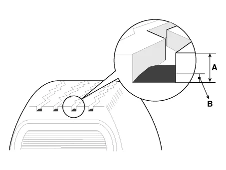
1.Measure the tread depth of the tires.
Tread depth [limit] : 1.6 mm (0.063 in)
2.If the remaining tread depth (A) is less than the limit, replace the tire.

ŌĆó When the tread depth of the tires is less than 1.6 mm(0.063 in), the wear indicators (B) will appear.
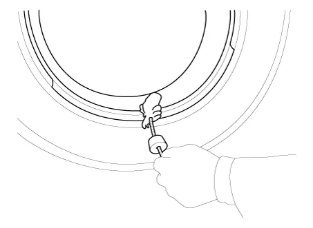
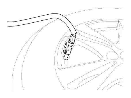
1.Remove valve core and deflate the tire.
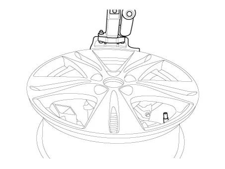
2.Remove the side of the tire bead area from the wheel using tire changing machine.
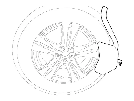

ŌĆó The tire bead should be broken approx. 90┬░ from the valve side of the wheel. The bead breaker should not be set too deep.
ŌĆó Avoid tire / tool contact with the valve on dismount.
ŌĆó Dismount should end near the valve.
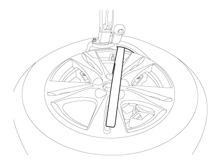
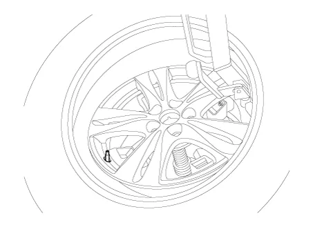
3. Rotate the wheel clockwise.
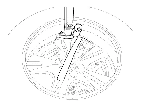
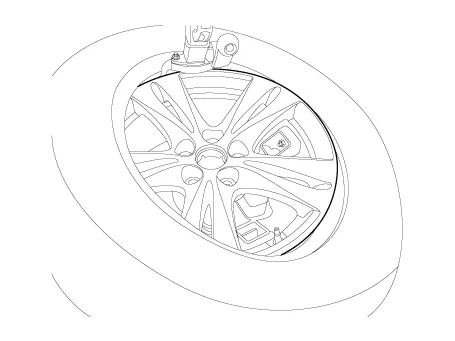
1. Apply tire soap or lubrication to the top and bottom tire beads.
2.To fit the bottom bead, position the valve at the 5 oŌĆÖclock position relative to the head on the tire changing machine.
3. Place the tire on the rim so the bottom bead touches the edge of the rim after the valve (6 oŌĆÖclock). Rotate the rim clockwise, and push down on the tire at the 3 oŌĆÖclock position to fit bottom bead.
4.After bottom bead is on tire, rotate the rim until the valve is at the 5 oŌĆÖclock position relative to the head on the tire changing machine. Push down on the tire at the 3 oŌĆÖclock position and rotate the rim clockwise to fit the top bead.
5.Inflate the tire until both beads seat.
Recommended Tire pressure : 230 kPa (33 psi)
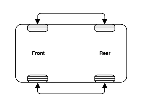
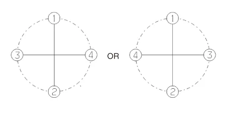
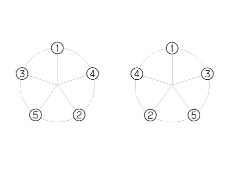
1.Rotate the front right and front left tires, and perform a road test in order to confirm vehicle stability.

2.If the steering pulls to the opposite side, rotate the front and rear tires, and perform a road test again.
3.If the steering continues to pull to one side, rotate the front right and left tires again, and perform a road test.
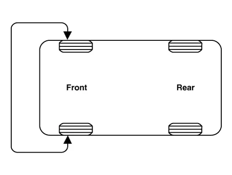
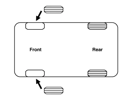
4.If the steering continues to pull to the opposite side, replace the front wheels with new ones.
Wheel
1.Tighten the hub nuts as follows.
Tightening torque :107.9 - 127.5 N.m (11.0 - 13.0 kgf.m, 79.6 - 94.0 lb-ft)

ŌĆó When using an impact gun, final tightening torque should be checked using a torque wrench.
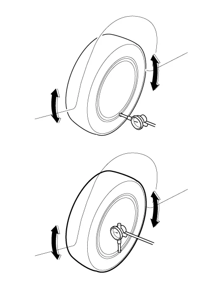
1.Jack up the vehicle.
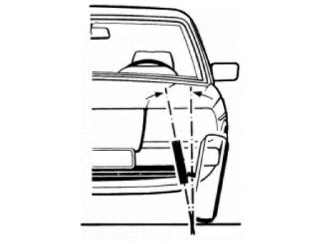
2.Measure the wheel Run-out by using a dial indicator as illustration below.
| Run-out | Aluminum |
| Radial mm (in.) | Below 0.3 (0.0118) |
| Lateral mm (in.) | Below 0.3 (0.0118) |
3.If measured value exceeds the standard value, replace the wheel.
Alignment

ŌĆó When using a commercially available computerized wheel alignment equipment to inspect the front wheel alignment, always position the vehicle on a level surface with the front wheels facing straight ahead.
ŌĆó Prior to inspection, make sure that the front suspension and steering system are in normal operating condition and that the tires are inflated to the specified pressure.

B - A ’╝× 0 : Toe in (+)B - A ’╝£ 0 : Toe out (-)
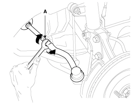
1.Loosen the tie rod end lock nut.
2.Remove the bellows clip to prevent the bellows from being twisted.
3.Adjust the toe by screwing or unscrewing the tie rod. Toe adjustment should be made by turning the right and left tie rods by the same amount.
Toe-inTotal : 0.15˚ ± 0.2˚Individual : 0.075˚ ± 0.1˚
4.When completing the toe adjustment, install the bellows clip and tighten the tie rod end lock nut to specified torque.
Tightening torque :49.0 - 53.9 N.m (5.0 - 5.5 kgf.m, 36.2 - 39.8 lb-ft)
| Camber angle | -0.5˚ ± 0.5˚ |
Caster angle : 4.64˚ ± 0.5˚
King-pin : 13.23˚ ± 0.5˚

ŌĆó The worn loose or damaged parts of the front suspension assembly must be replaced prior to measuring front wheel alignment.
ŌĆó Caster are pre-set to the specified value at the factory and don't need to be adjusted.
ŌĆó If the caster are not within specifications, replace bent or damaged parts.
ŌĆó The difference of left and right wheels about the the caster must be within the range of 0┬░ ┬▒ 0.5┬░.

ŌĆó When using a commercially available computerized wheel alignment equipment to inspect the rear wheel alignment, always position the vehicle on a level surface.
ŌĆó Prior to inspection, make sure that the rear suspension system is in normal operating condition and that the tires are inflated to the specified pressure.
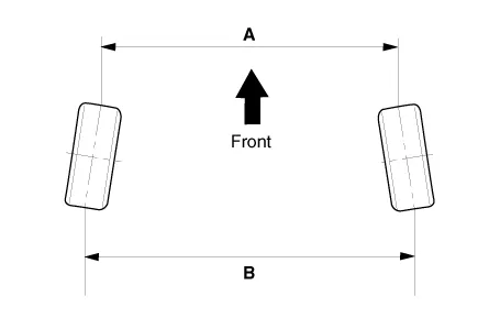
B - A ’╝× 0 : Toe in (+)B - A ’╝£ 0 : Toe out (-)
Toe is pre-set at the factory, so it does not need to be adjusted. If the toe is not within the standard value, replace or repair the damaged parts and then inspect again.| Toe-in | Total | 0.3┬░ ┬▒ 0.3┬░ |
| Individual | 0.15┬░ ┬▒ 0.15┬░ |
Camber angle : -1.5˚ ± 0.5˚


Other information:
Hyundai Accent (HC) (2017 - 2022) Service Manual: General Safety Information and Caution
- Instructions ŌĆó The R-1234yf liquid refrigerant is flammable gas. The gas reduces oxygen available for breathing and causes asphyxiation in high concentrations. The victim will not realize that he/she is suffocating. ŌĆó Inhalation may cause central nervous system effects and may cause drowsiness and dizziness. ŌĆó Ingestion may cause gastrointestinal discomfort.Hyundai Accent (HC) (2017 - 2022) Service Manual: Explanation of scheduled maintenance items
Engine Oil and Filter The engine oil and filter should be changed at the intervals specified in the maintenance schedule. If the Hyundai Accent is being driven in severe conditions, more frequent oil and filter changes are required to protect the engine from accelerated wear and sludge buildup. Drive Belts Inspect all drive belts for evidence of cuts, cracks, excessive wear or oil saturation and replace if necessary.
Contents
Categories
- Manuals Home
- Hyundai Accent Owners Manual
- Hyundai Accent Service Manual
- Questions & Answers
- Video Guides
- Useful Resources
- New on site
- Most important about car
- Privacy Policy

0.0068