Hyundai Accent (HC): Suspension System / Rear Suspension System
Contents:
Components and Components Location
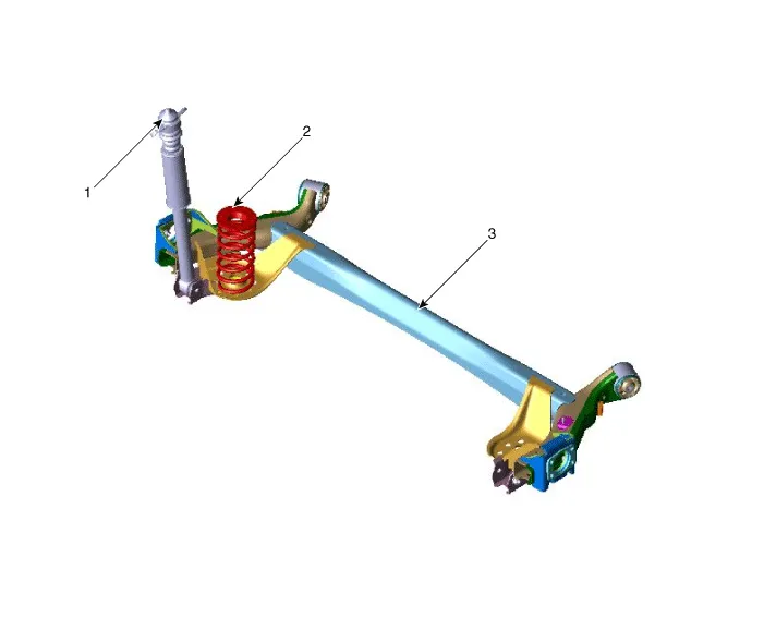
1. Rear shock absorber
2. Coil spring
3. Torsion beam axle
Rear Shock Absorber
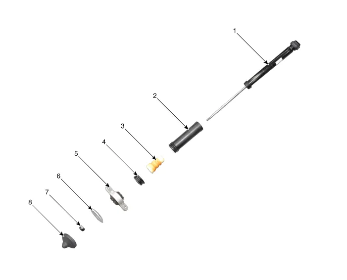
1. Rear shock absorber
2. Dust cover
3. Bumper rubber
4. Cup
5. Insulator
6. Retainer
7. Lock nut
8. Insulator cover
1.Loosen the wheel nuts slightly.Raise the vehicle, and make sure it is securely supported.
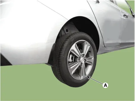
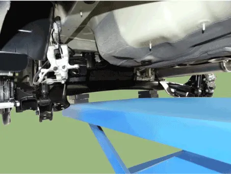
2.Remove the rear wheel and tire (A) from front hub.
Tightening torque :107.9 - 127.5 N.m (11.0 - 13.0 kgf.m, 79.6 - 94.0 lb-ft)


• Be careful not to damage the hub bolts when removing the rear wheel and tire.
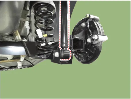
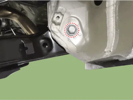
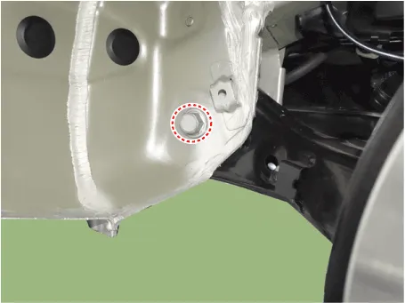
3.Remove the rear shock absorber (A) from the frame by loosening the bolt.
Tightening torque :49.0 - 63.7 N.m (5.0 - 6.5 kgf.m, 36.2 - 47.0 lb-ft)
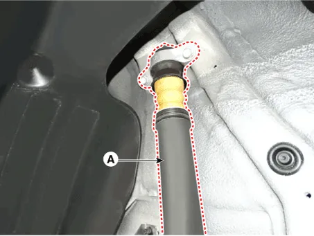

• Install the jack under the torsion beam axle when removing the rear shock absorber.
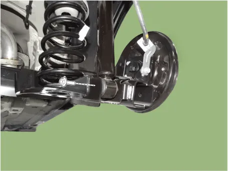
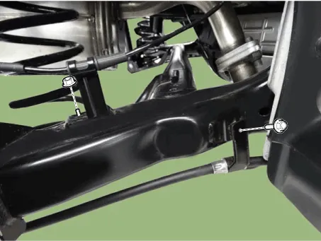
4.Loosen the bolt & nut and then remove the rear shock absorber from the torsion beam axle.
Tightening torque :98.1 - 117.7 N.m (10.0 - 12.0 kgf.m, 72.3 - 86.8 lb-ft)


5.Install the other parts in the reverse order of removal.
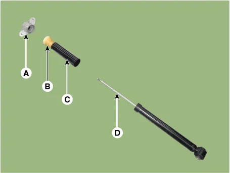
1.Remove the lock nut cover (A).
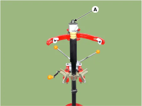
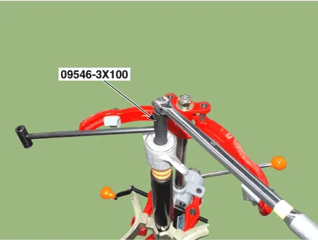
2.Using the special tool (09546-3X100), remove the self locking nut.

3.Separate the bracket assembly (A), bumper rubber (B), dust cover (C), shock absorber (D).
1.Remove the strike cap (A) from the shock absorber assembly.
2.Remove the gas by Drilling a hole in the inner oil seal.
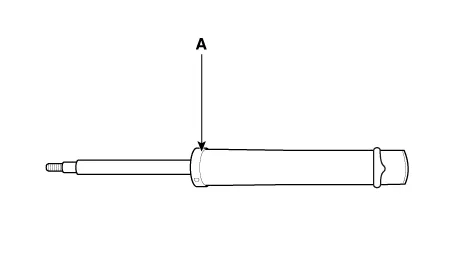

• The gas coming out is harmless but be careful of chips that may fly when drilling.
1.To reassembly, reverse the disassembly procedure.
2.Using SST (09546-3X100), install the lock nut.
Tightening torque :21.6 - 31.4 N.m (2.2 - 3.2 kgf.m, 15.9 - 23.1 lb-ft)

• Do not reuse the self locking nut.
3.Install the lock nut cover (A).

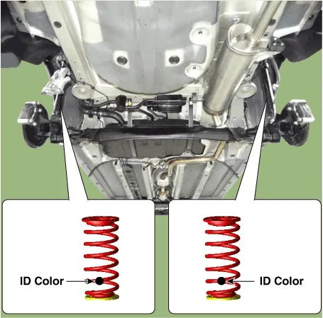
Rear Coil Spring
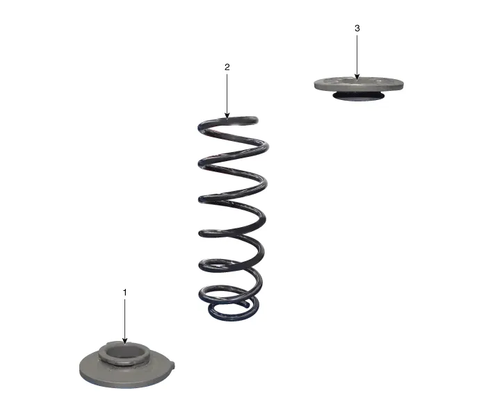
1. Spring lower pad
2. Coil spring
3. Spring upper pad
1.Loosen the wheel nuts slightly.Raise the vehicle, and make sure it is securely supported.
2.Remove the rear wheel and tire (A) from front hub.
Tightening torque :107.9 - 127.5 N.m (11.0 - 13.0 kgf.m, 79.6 - 94.0 lb-ft)

• Be careful not to damage the hub bolts when removing the rear wheel and tire.
3.Loosen the bolt & nut and then remove the rear shock absorber from the torsion beam axle.
Tightening torque :98.1 - 117.7 N.m (10.0 - 12.0 kgf.m, 72.3 - 86.8 lb-ft)

• Install the jack under the torsion beam axle when removing the rear shock absorber.
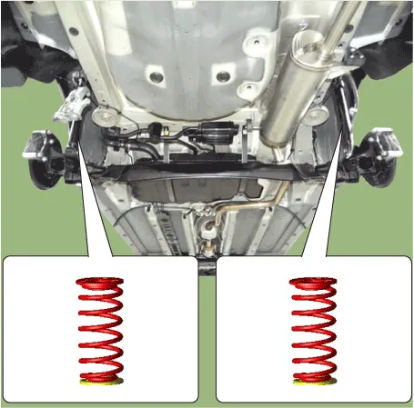
4.Remove the coil spring.
5.Install the other parts in the reverse order of removal.
1.Install in the reverse order of removal.

• The ID Color should be faced backward of vehicle when installing the coil spring.
Rear Torsion Beam Axle
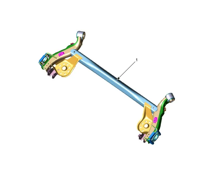
1. Torsion beam axle
1.Loosen the wheel nuts slightly.Raise the vehicle, and make sure it is securely supported.
2.Remove the rear wheel and tire (A) from front hub.
Tightening torque :107.9 - 127.5 N.m (11.0 - 13.0 kgf.m, 79.6 - 94.0 lb-ft)


• Be careful not to damage the hub bolts when removing the rear wheel and tire.
3.Remove the brake caliper from the torsion beam axle.(Refer to Brake System - "Rear Disc Brake")
4.Remove the rear hub assembly.(Refer to Dirveshaft and axle - "Rear Axle assembly")
5.Loosen the bolt & nut and then remove the rear shock absorber from the torsion beam axle.
Tightening torque :98.1 - 117.7 N.m (10.0 - 12.0 kgf.m, 72.3 - 86.8 lb-ft)


• Install the jack under the torsion beam axle when removing the rear shock absorber.
6.Remove the coil spring.


• The ID Color should be faced backward of vehicle when installing the coil spring.

7.Remove the wheel speed sensor cable bracket and parking brake cable bracket.
Tightening torque :8.8 - 13.7 N.m (0.9 - 1.4 kgf.m, 6.5 - 10.1 lb-ft)
8.Loosen the mounting bolt and then remove the torsion beam axle.
Tightening torque :117.7 - 137.3 N.m (12.0 - 14.0 kgf.m, 86.8 - 101.3 lb-ft)

• Install the jack under the torsion beam axle when removing the torsion beam axle.
9.Install the other parts in the reverse order of removal.
10.Check the front alignment.(Refer to Suspension System - "Front Alignment")
1.Remove the rear torsion beam axle from the vehicle.(Refer to Rear Torsion Beam Axle - "Removal")
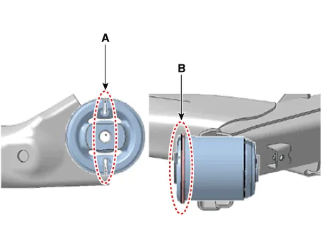
2.Using the SST (09551-AL100) and press, replace the bush (A).
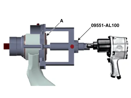

• When press in the bush, press the same direction of the void (A) and the flange direction (B) before detaching.


Other information:
Hyundai Accent (HC) (2017 - 2022) Service Manual: CVVT & Camshaft
- Description Continuous Variable Valve Timing (CVVT) system advances or retards the valve timing of the intake and exhaust valve in accordance with the ECM control signal which is calculated by the engine speed and load.By controlling CVVT, the valve over-lap or under-lap occurs, which makes better fuel economy and reduces exhaust gases (NOx, HC) and improves engine performance through reduction of pumping loss, internal EGR effect, improvement of combustion stability, improvement of volumetric efficiency, and increase of expansion work.Hyundai Accent (HC) (2017 - 2022) Service Manual: Description and Operation
- Description The SMART KEY system is a system that allows the user to access and operate a vehicle in a very convenient way. To access the vehicle, no traditional key or remote control unit is needed.The user carries a SMART KEY FOB which does not require any conscious actions by the user (e.g. operate a RKE button). The SMART KEY system is triggered by pressing a push button in the door handle.
Contents
Categories
- Manuals Home
- Hyundai Accent Owners Manual
- Hyundai Accent Service Manual
- Questions & Answers
- Video Guides
- Useful Resources
- New on site
- Most important about car
- Privacy Policy

0.0114