Hyundai Accent (HC): Suspension System / Front Suspension System
Contents:
- Components and Components Location
- Front Strut Assembly
- Front Lower Arm
- Front Lower Arm G Bushing
- Front Stabilizer Bar
- Sub Frame
Components and Components Location
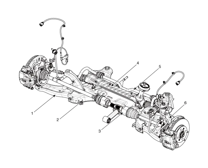
1. Front lower arm
2. Sub frame
3. Driveshaft
4. Steering gear box
5. Front stabilizer bar
6. Front axle assembly
Front Strut Assembly
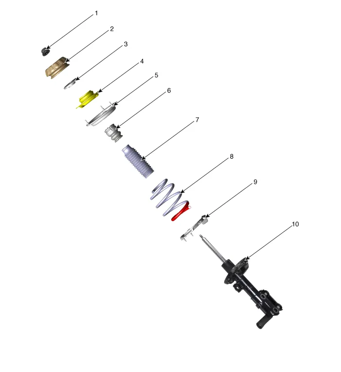
1. Lock nut
2. Insulator
3. Strut bearing
4. Spring upper seat
5. Spring upper pad
6. Bumper rubber
7. Dust cover
8. Coli spring
9. Spring lower pad
10. Front shock absorber
1.Loosen the wheel nuts slightly.Raise the vehicle, and make sure it is securely supported.
2.Remove the front wheel and tire (A) from the front hub.
Tightening torque :107.9 - 127.5 N.m (11.0 - 13.0 kgf.m, 79.6 - 94.0 lb-ft)


• Be careful not to damage the hub bolts when removing the front wheel and tire.
3.Loosen the mounting bolt and then remove the wheel speed sensor cable from the strut assembly.
Tightening torque :7.8 - 11.8 N.m (0.8 - 1.2 kgf.m, 5.8 - 8.7 lb-ft)
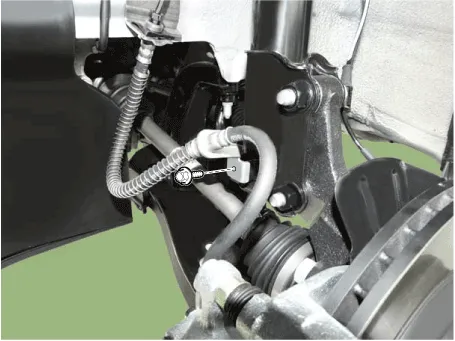
4.Loosen the mounting bolt and then remove the brake hose from the strut assembly.
Tightening torque :8.8 - 13.7 N.m (0.9 - 1.4 kgf.m, 6.5 - 10.1 lb-ft)
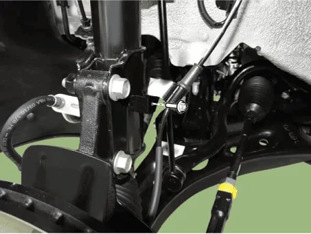
5.Disconnect the stabilizer link with the front strut assembly after loosening the nut (A).
Tightening torque :98.1 - 117.7 N.m (10.0 - 12.0 kgf.m, 72.3 - 86.8 lb-ft)
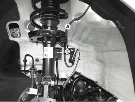

• When loosening the nut (A), fix the outer hexagon of stabilizer bar link.
• Be careful not to damage the stabilizer link boots.
6.Remove the cowl top cover.(Refer to Body - "Cowl Top Cover")
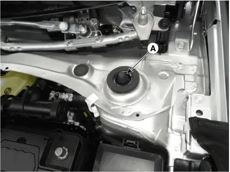
7.Remove the lock nut cover (A).
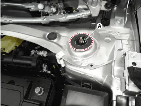
8.Loosen the upper strut mounting nut (A).
Tightening torque :68.6 - 78.5 N.m (7.0 - 8.0 kgf.m, 50.6 - 57.9 lb-ft)
9.Remove the front strut assembly from the front knuckle (A).
Tightening torque :98.1 - 117.7 N.m (10.0 - 12.0 kgf.m, 72.3 - 86.8 lb-ft)
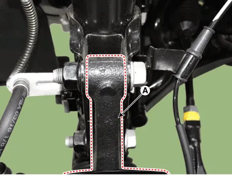

• Be careful not to damage the driveshaft, front sub frame or stabilizer link.
10.Install the other parts in the reverse order of removal.

• When compressing the coil spring, be cautious as there may be corrosion due to damage to the coil spring painting. In order to avoid such painting damage, compress by putting over the waste hose, etc. (Refer to the picture below.)
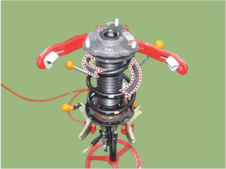
1.Using the spring compressor, compress the coil spring.
Tightening torque :68.6 - 78.5 N.m (7.0 - 8.0 kgf.m, 50.6 - 57.9 lb-ft)
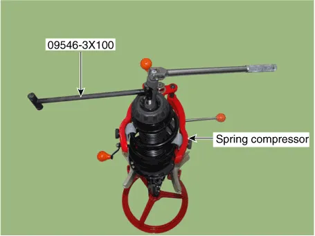
2.Remove the self-locking nut from the strut assembly.
3.Remove the insulator, spring seat, coil spring and dust cover from the strut assembly.
4.Reassembly is the reverse of the disassembly.
1.Check the strut bearing for wear and damage.
2.Check the spring upper and lower pad for damage and deterioration.
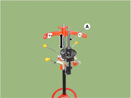
3.Compress and extend the piston rod (A) and check that there is no abnormal resistance or unusual sound during operation.
1.Fully extend the piston rod.
2.Drill a hole on the (A) section to remove gas from the cylinder.
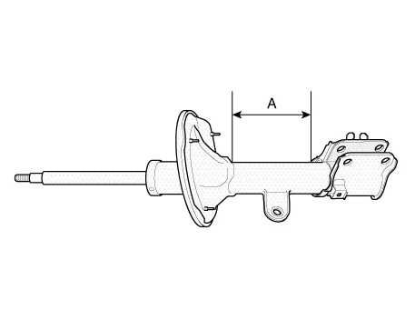

• The gas coming out is harmless, but be careful of chips that may fly when drilling.
• Be sure to wear safety goggles or eye protection when performing this task.
Front Lower Arm
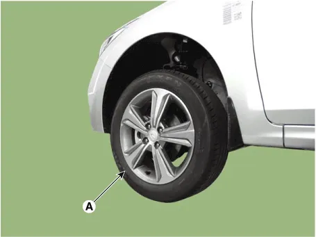
1.Loosen the wheel nuts slightly.Raise the vehicle, and make sure it is securely supported.
2.Remove the front wheel and tire (A) from the front hub.
Tightening torque :107.9 - 127.5 N.m (11.0 - 13.0 kgf.m, 79.6 - 94.0 lb-ft)


• Be careful not to damage the hub bolts when removing the front wheel and tire.
3.Loosen the lower arm nut (A) and then remove the lower arm ball joint by using SST(09568-1S100).
Tightening torque :58.8 - 70.6 N.m (6.0 - 7.2 kgf.m, 43.4 - 52.1 lb-ft)

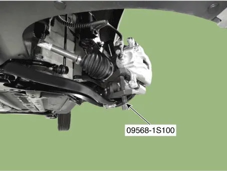

• Do not reuse the lower arm lock nut (A).
• Be careful not to damage the ball joint boots.
4.Remove the front lower (A) arm after loosening the bolts & nuts.
Tightening torqueFront : 117.7 - 137.3 N.m (12.0 - 14.0 kgf.m, 86.8 - 101.3 lb-ft)Rear : 156.9 - 176.5 N.m (16.0 - 18.0 kgf.m, 115.7 - 130.2 lb-ft)
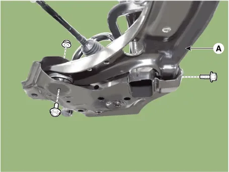

• Tighten the front mounting bolt first and then tighten the rear mounting bolt and nut.
5.Install the other parts in the reverse order of removal.
6.Check the wheel Alignment.(Refer to Tires/Wheels - "Alignment")
1.Check the bushing for wear and deterioration.
2.Check the lower arm for deformation.
3.Check the all bolts and nuts.
Front Lower Arm G Bushing

• Replace the lower arm G bushing if it only has a crack, noise from bushing without cracks can be improved by applying silicone oil.
1.Replace the lower arm G bushing by using the SST (09545-AL100).
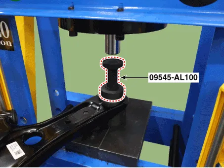
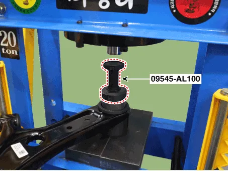

• Refer to the enclosed manual for detailed usage instructions of the lower arm G bushing SST(09545-AL100).

• Wear personal protective equipment during press operation.
• When the press is in operation, ensure that no part of the body comes into contact within the operating range.
• Due to the risk of injury from falling tools and parts, before operating the press, ensure that all tools and components are securely positioned in their proper places.

• Lubricate the bushings and mounting surface with grease during the operation.
• Measure the void spacing (A), (B) to ensure that the bushing can be properly installed in the correct direction.
(A) : Ball joint side(B) : Opposite side
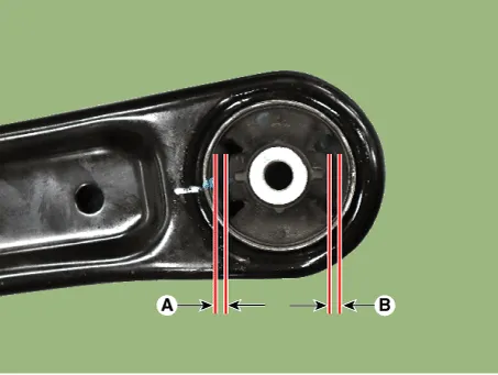
• Be careful not to install the bushing at the incorrect angle.
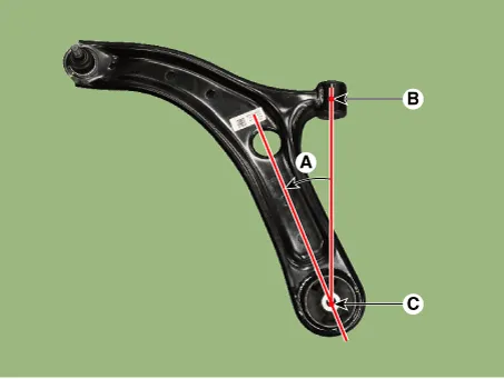
Installation angle (A) : Angle formed counterclockwise from A bushing (B) and G bushing (C) reference
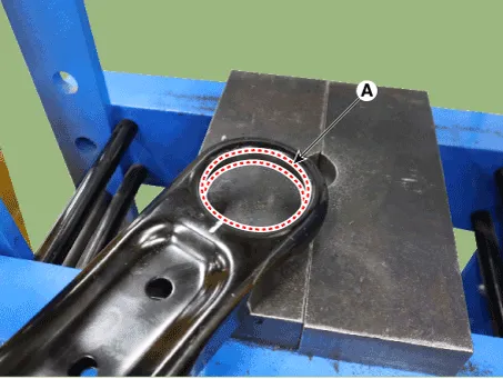
• Clean the bushing mounting surface (A) from any foreign substances using a clean cloth or similar material when installing.
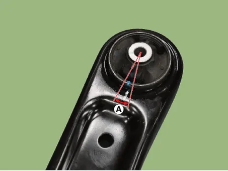
• Ensure that the marking angle (A) of the bushing and the lower arm does not deviate from the reference value.
Reference Value : ± 3°
• If excessive pressure is applied after installation is complete, it may result in damage to the components and tools.
Front Stabilizer Bar
1.Loosen the wheel nuts slightly.Raise the vehicle, and make sure it is securely supported.
2.Remove the front wheel and tire (A) from the front hub.
Tightening torque :107.9 - 127.5 N.m (11.0 - 13.0 kgf.m, 79.6 - 94.0 lb-ft)

• Be careful not to damage the hub bolts when removing the front wheel and tire.
3.Disconnect the stabilizer link with the front strut assembly after loosening the nut (A).
Tightening torque :98.1 - 117.7 N.m (10.0 - 12.0 kgf.m, 72.3 - 86.8 lb-ft)


• When loosening the nut (A), fix the outer hexagon of stabilizer bar link. •
• Be careful not to damage the stabilizer link boots.
4.Remove the tie rod end ball joint.
(1)Remove the split pin (C).
(2)Loosen the nut (B).
(3)Using SST(09568-1S100), separate the ball joint (A) from the knuckle.
Tightening torque :24.5 - 34.3 N.m (2.5 - 3.5 kgf.m, 18.1 - 25.3 lb-ft)
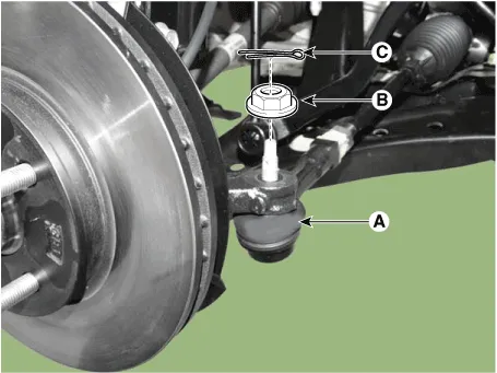

• Do not reuse the split pin (C).
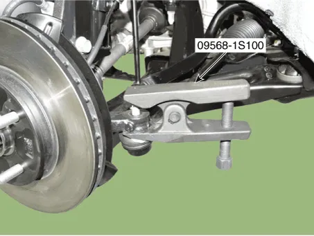
5.Loosen the lower arm nut (A) and then remove the lower arm ball joint by using SST(09568-1S100).
Tightening torque :58.8 - 70.6 N.m (6.0 - 7.2 kgf.m, 43.4 - 52.1 lb-ft)


• Do not reuse the lower arm lock nut (A).
• Be careful not to damage the ball joint boots.
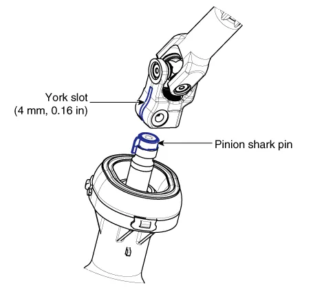
6.Loosen the bolt (A) and then disconnect the universal joint assembly from the pinion of the steering gear box.
Tightening torque : M8 BOLT : 32.4 - 37.3 N.m (3.3 - 3.8 kgf.m, 23.9 - 27.5 lb-ft)M10 BOLT : 49.0 - 58.8 N.m (5.0 - 6.0 kgf.m, 36.2 - 43.4 lb-ft)


• Do not reuse the bolt.
• Lock the steering wheel in the straight ahead position to prevent the damage of the clock spring inner cable.
• When assembling, insert the shark pin into the universal joint york slot as the illustration below.

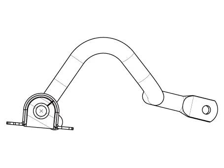
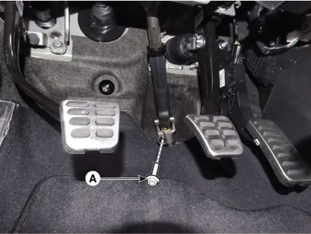
7.Remove the roll rod stopper by loosening the bolt and nut.
Tightening torque :107.9 - 127.5 N.m (11.0 - 13.0 kgf.m, 79.6 - 94.0 lb-ft)

8.Remove the muffler rubber hanger (A).

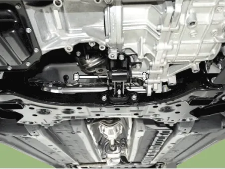
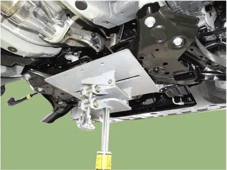
9.Remove the subframe by loosening the mounting bolts and nuts.
Tightening torque 176.5 - 196.1 N.m (18.0 - 20.0 kgf.m, 130.2 - 144.7 b-ft)
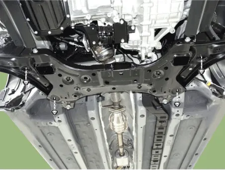

• Set a transmission jack for safety.

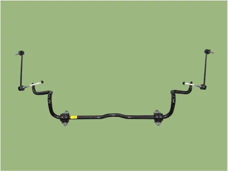
10.Loosen the mounting bolts and then remove the stabilizer bar (A).
Tightening torque :44.1 - 53.9 N.m (4.5 - 5.5 kgf.m, 32.5 - 39.8 lb-ft)
11.Remove the stabilizer link.
Tightening torque :98.1 - 117.7 N.m (10.0 - 12.0 kgf.m, 72.3 - 86.8 lb-ft)
12.Remove the bushing.
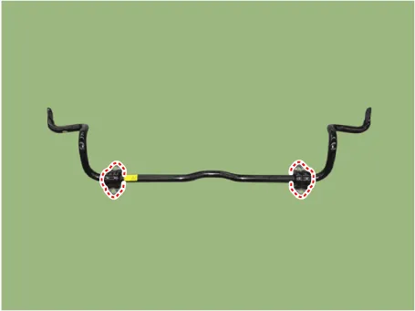

• When installing, assemble slit of bush is located in the direction shown.
13.Install the other parts in the reverse order of removal.
14.Check the wheel Alignment.(Refer to Tires/Wheels - "Alignment")
1.Check the bushing for wear and deterioration.
2.Check the front stabilizer bar for deformation.
3.Check the front stabilizer link ball joint for damage.
Sub Frame
1.Loosen the wheel nuts slightly.Raise the vehicle, and make sure it is securely supported.
2.Remove the front wheel and tire (A) from the front hub.
Tightening torque :107.9 - 127.5 N.m (11.0 - 13.0 kgf.m, 79.6 - 94.0 lb-ft)


• Be careful not to damage the hub bolts when removing the front wheel and tire.
3.Disconnect the stabilizer link with the front strut assembly after loosening the nut (A).
Tightening torque :98.1 - 117.7 N.m (10.0 - 12.0 kgf.m, 72.3 - 86.8 lb-ft)


• When loosening the nut (A), fix the outer hexagon of stabilizer bar link.
• Be careful not to damage the stabilizer link boots.
4.Remove the tie rod end ball joint.
(1)Remove the split pin (C).
(2)Loosen the nut (B).
(3)Using SST(09568-1S100), separate the ball joint (A) from the knuckle.
Tightening torque :24.5 - 34.3 N.m (2.5 - 3.5 kgf.m, 18.1 - 25.3 lb-ft)


• • Do not reuse the split pin (C).
5.Loosen the lower arm nut (A) and then remove the lower arm ball joint by using SST(09568-1S100).
Tightening torque : 58.8 - 70.6 N.m (6.0 - 7.2 kgf.m, 43.4 - 52.1 lb-ft)


• Do not reuse the lower arm lock nut (A).
• Be careful not to damage the ball joint boots.
6.Loosen the bolt (A) and then disconnect the universal joint assembly from the pinion of the steering gear box.
Tightening torque : M8 BOLT : 32.4 - 37.3 N.m (3.3 - 3.8 kgf.m, 23.9 - 27.5 lb-ft)M10 BOLT : 49.0 - 58.8 N.m (5.0 - 6.0 kgf.m, 36.2 - 43.4 lb-ft)

• Do not reuse the bolt.
• Lock the steering wheel in the straight ahead position to prevent the damage of the clock spring inner cable.
• When assembling, insert the shark pin into the universal joint york slot as the illustration below.
7.Remove the roll rod stopper by loosening the bolt and nut.
Tightening torque :107.9 - 127.5 N.m (11.0 - 13.0 kgf.m, 79.6 - 94.0 lb-ft)
8.Remove the muffler rubber hanger (A).
9.Remove the subframe by loosening the mounting bolts and nuts.
Tightening torque Sub frame mounting bolts and nut : 176.5 - 196.1 N.m (18.0 - 20.0 kgf.m, 130.2 - 144.7 b-ft)


• Set a transmission jack for safety.
10.Loosen the mounting bolts and then remove the stabilizer bar (A).
Tightening torque : 44.1 - 53.9 N.m (4.5 - 5.5 kgf.m, 32.5 - 39.8 lb-ft)

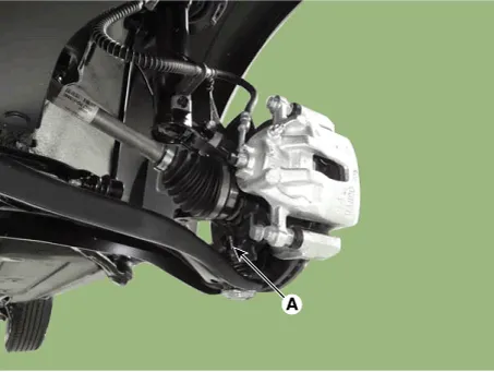
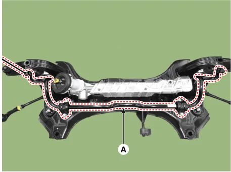
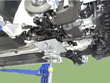
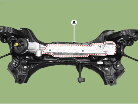
11.Remove the protector (A).
Tightening torque : 6.9 - 10.8 N.m (0.7 - 1.1 kgf.m, 5.1 - 8.0 lb-ft)
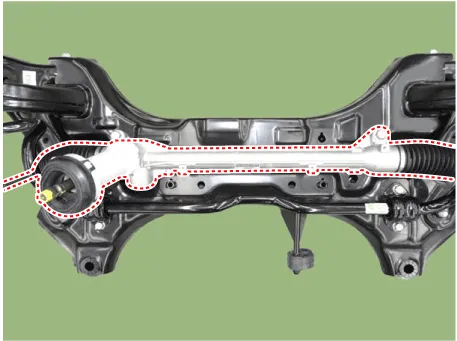
12.Remove the steering gearbox from the front sub frame by loosening the mounting bolts.
Tightening torque : 88.2 - 107.8 N.m (9.0 - 11.0 kgf.m, 65.0 - 79.5 lb-ft)
13.Remove the front lower (A) arm after loosening the bolts & nuts.
Tightening torqueFront : 117.7 - 137.3 N.m (12.0 - 14.0 kgf.m, 86.8 - 101.3 lb-ft)Rear : 156.9 - 176.5 N.m (16.0 - 18.0 kgf.m, 115.7 - 130.2 lb-ft)


• Tighten the front mounting bolt first and then tighten the rear mounting bolt and nut.
14.Install the other parts in the reverse order of removal.
15.Check the wheel Alignment.(Refer to Tires/Wheels - "Alignment")


Other information:
Hyundai Accent (HC) (2017 - 2022) Service Manual: LCD Display Modes
The information provided may differ depending on which functions and options are available for your specific Hyundai Accent configuration. Engage parking brake to edit settings/Shift to P to edit settings This warning message appears if you attempt to adjust User Settings while driving. - Manual transmission For your safety, change User Settings only after parking the vehicle, applying the parking brake, and moving the shift lever to neutral.Hyundai Accent (HC) (2017 - 2022) Service Manual: Exterior Care
NOTICE If you park your Hyundai Accent near a stainless steel sign or glass facade building, the vehicle's exterior plastic parts such as a bumper, spoiler, garnish, lamp or outside rearview mirror might be damaged due to sunlight reflected from the sign or building. To prevent damage of the exterior plastic parts, you should avoid parking in areas where light may be reflected or use a car cover.
Contents
- Components and Components Location
- Front Strut Assembly
- Front Lower Arm
- Front Lower Arm G Bushing
- Front Stabilizer Bar
- Sub Frame
Categories
- Manuals Home
- Hyundai Accent Owners Manual
- Hyundai Accent Service Manual
- Questions & Answers
- Video Guides
- Useful Resources
- New on site
- Most important about car
- Privacy Policy

0.0094