Hyundai Accent (HC): Suspension System / Tire Pressure Monitoring System
Contents:
- Components and Components Location
- Schematic Diagrams
- Description and Operation
- TPMS Sensor
- TPMS Receiver
Components and Components Location

1. TPMS Receiver
2. TPMS Sensor (FL)
3. TPMS Sensor (RL)
4. TPMS Sensor (RR)
5. TPMS Sensor (FR)
Schematic Diagrams
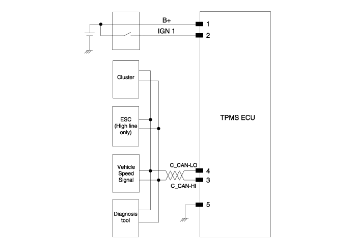

| Pin No. | Function | Description |
| 1 | Battery | VBAT |
| 2 | IG ON | Battery to IG ON |
| 3 | CAN_High | CAN_High |
| 4 | CAN_Low | CAN_Low |
| 5 | Ground | Battery to ground |
| 6 | - | - |
Description and Operation


TPMS Sensor

1.General descriptionWU is a sensor placed in the tire that reports pressure and temperature.The WU is mounted inside the wheels, fixed to the valve. The angle between the valve and the housing of the WU is variable.This allows adaptation to various types of rims.The Wheel Unit is made of a PCB supporting the electronic hardware and encapsulated inside a housing which is potted with polyurethane.It is self-powered by a battery and includes all systems for parameter measurement (pressure, temperature and centrifugal acceleration and optionally rotation direction), RF transmission and LF detection.To achieve the specified battery lifetime, the WU supports various measurement and transmission timings, depending on WU operation mode.For RF transmission, WU uses an internal antenna.
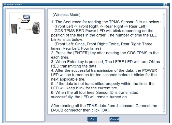
2.First Block Mode: When vehicle start driving, Sensor enter Mode First Block. Typical period of RF emissions is 16 sec. for 40 times for Auto-learning and Auto-location function.
3.Driving Mode: After 19 min. parking and then finishing Mode First Block mode, WU enter Driving mode.Typical period of RF emissions are 64 sec above 4g vehicle speed.
4.Parking Mode: at below 3g Vehicle speed, enter Parking mode. Typical periodicities of RF emissions are 13 hours.
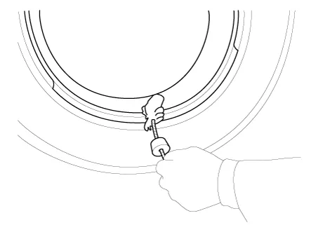
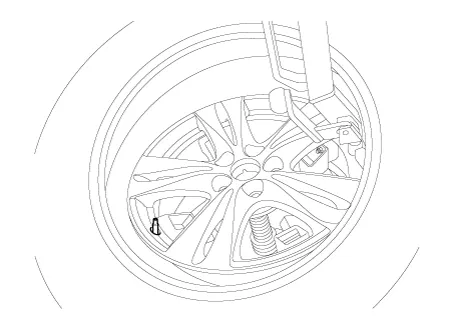
1.Remove the valve core and deflate the tire.
2.Remove the side of the tire bead area from the wheel using tire changing machine.


• The tire bead should be broken approx. 90° from the valve side of the wheel. The bead breaker should not be set too deep.
• Avoid tire/tool contact with the valve on dismount.
• Dismount should end near the valve.
3.Rotate the wheel clockwise.
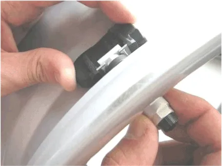
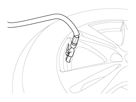
4.The valve during transportation (air inlet portion of the silver) deviated from its original location be sure to check whether the original position of the valve (metal brackets) are assembled in indented state.
5.While tightening the nut on the valve as not to deviate from the fixed position while rotating the valve to a fixed location (metal brackets to fit inside) and push. The specified torque (8Nm) to tighten the nut does not reuse.
6.Contact with the rim so that the valve washer seals the valve hole put into.

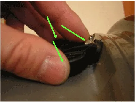
7.Housing with two fingers holding the valve in the axial direction with one finger and push the valve.
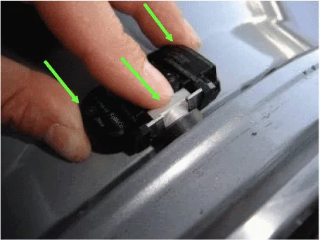
8.Housing, the state must be visible laser marking.
9.When the valve is fully inserted so that the contact between the sensor and the rim while keeping hands on the wheel nut tightening will start Wed.

10.While maintaining the position of the valve and the sensor is mounted nut.
11.Apply tire soap or lubrication to the top and bottom tire beads.
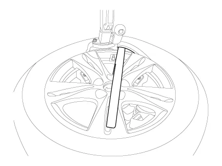
12.To fit the bottom bead, position the sensor at the 5 o’clock position relative to the head on the tire changing machine
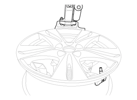
13.Place the tire on the rim so the bottom bead touches the edge of the rim after the sensor (@6 o’clock). Rotate the rim clockwise, and push down on the tire at the 3 o’clock position to fit bottom bead.
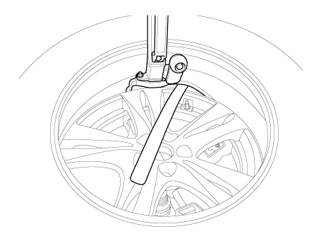
14.After bottom bead is on tire, rotate the rim until the sensor is at the 5 o’clock position relative to the head on the tire changing machine. Push down on the tire at the 3 o’clock position and rotate the rim clockwise to fit the top bead.
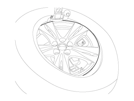
15.Inflate the tire until both beads seat.
16.In the case of TPMS sensor failure, TPMS sensor needs learning. Faulty sensor is replaced new units, conduct learning of TPMS sensors.
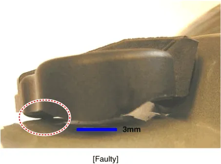
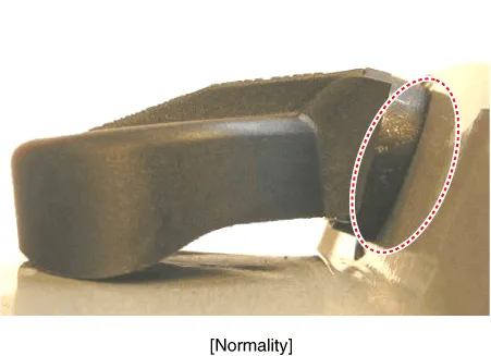
1.Sealing washer on the outside rim of hole to be compressed.
2.The lower part of the valve housing, a fixed place (no metal brackets) should be located.
3.Housing is at least one or more points on the surface of the rim should contact.
4.The rim of the housing mounting height shall not exceed the height of the chin.
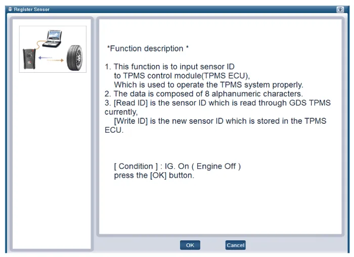
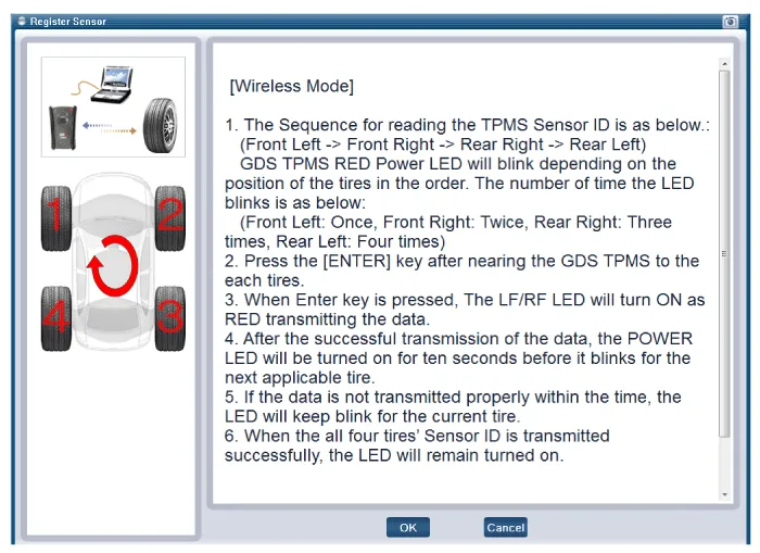
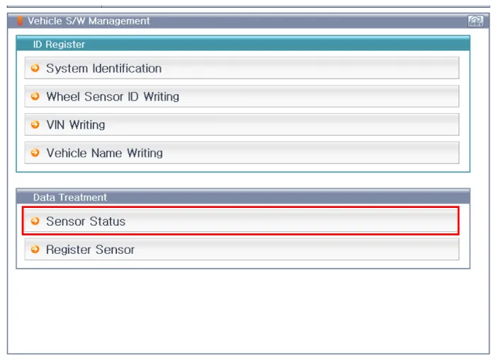
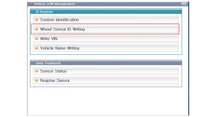
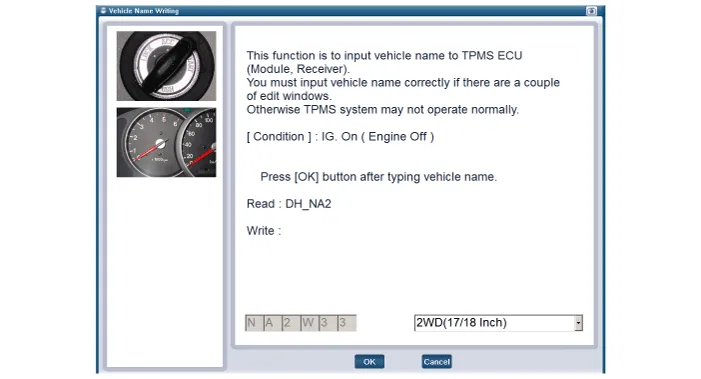
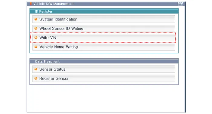
1.Connect self-diagnosis connector(16pins) located in the lower of driver side crash pad to self-diagnosis device, and then turn the self-diagnosis device after key is ON.
2.Select the "vehicle model" and "TPMS" on GDS vehicle selection screen, then select OK.
1.Connect the diagnostic instrument to the self-diagnostic connector (16-pin) beneath the crash pad on the side of driver's seat, and then turn on the ignition to activate the diagnostic instrument.
2.In the GDS Vehicle Type Selection menu, select "Vehicle Type" and "TPMS" System, and then opt for "OK."

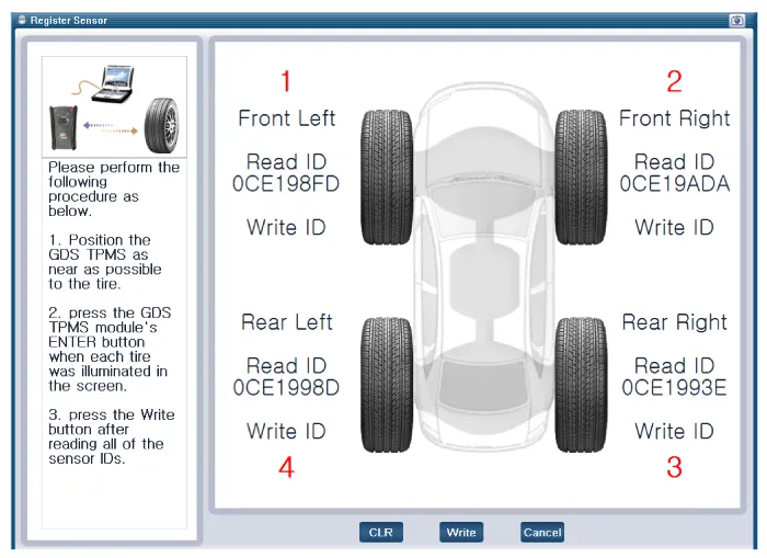
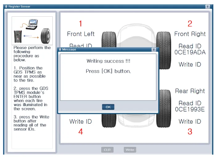
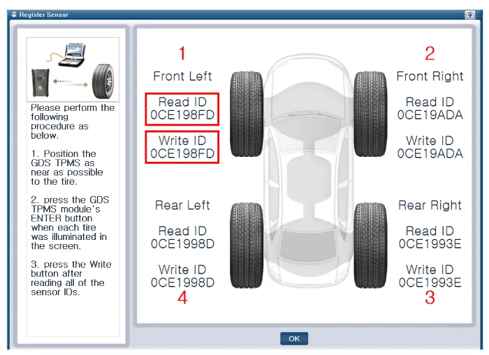

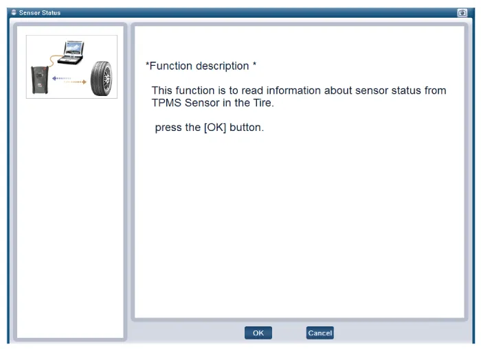
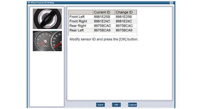
• Make sure that the read ID matches the written ID.
• After successfully registering the sensor, proceed to "Sensor Wireless Information" to ensure that the sensor functions correctly.
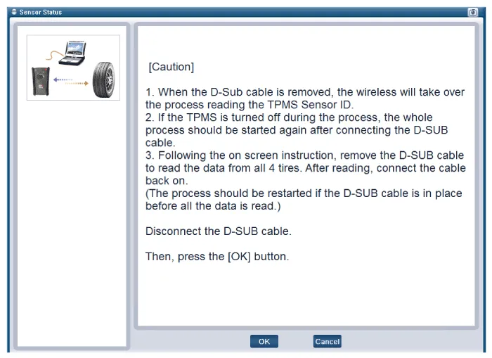

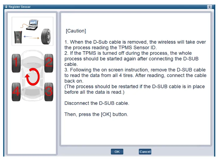
• In North America, the cable is measured separately.
• In Domestic/General(European) area, the cable is measured without separation.

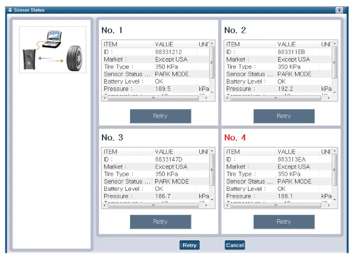

• Check each sensor component to ensure that it functions correctly.
• Replace any tires or sensors that do not function correctly, proceed to the sensor registration procedure, and check if the sensors function correctly.
TPMS Receiver

1.FunctionThe TPMS monitors the pressure and temperature of the tires and warns the driver of changes that could potentially influence driving conditions.The cluster warning lamp displays the messages generated from processing the data. The ECU processes the data received from the WE sensor, determines the conditions of the tire, and then sends any necessary warning signals to the driver through the CAN line or hard wire control line.
2.Mode
(1)Virgin Mode
• This mode is active when a unit is stocked as a part for after-sales service, meaning that there is no data concerning the vehicle code, wheel size, and sensor ID stored in its memory.
• In this mode, the receiver does not save any RF signals it receives from the pressure sensors, nor does it control the warning lamp.
• It also does not detect or memorize DTCs, and it does not perform the Auto Learning and Auto Location functions.
• After turning the ignition on, use a diagnostic instrument (GDS etc.) or TPMS exciter to enter the vehicle code/wheel size/sensor ID. This changes the current mode to Normal.
(2)Normal Mode
• This is the mode applied when the vehicle is shipped from the factory.
• It performs all of the standard TPMS functions.
• Check the system warning lamp (TPMS lamp) to determine the current mode of the TPMS receiver.
• In virgin mode: When the IG turns ON, it remains ON for 3 seconds and then blinks every half second.
• In normal mode: When the IG turns ON, it remains ON for 3 seconds and then turns OFF. (However, it remains ON if a DTC exists.)
1.General Function
• Auto-locate/learn takes place only once per Ignition cycle.
• On successful completion, 4 road wheel sensor ID's, together with their respective road wheel positions are latched into memory for monitoring.
• Until Auto-learn completes, previously learned sensors (together with their respective locations) are monitored for under inflation / leak warnings.
• Spare tire inflation / DTC state is not displayed.
2.General Conditions to Learn New Sensors:
• Receiver must Auto-Locate 4 road sensors.
• Auto-location / learning only functions when speed is more than 20 kph (approx. 15 mph).
• Receiver must determine that it is confident that sensor is not temporary:
a.Uses vehicle speed.
b.Uses confidence reduction of previously learned sensors.
• Typical time at driving over 20 kph to learn a new sensor is up to 10 minutes.
3.General Conditions to Un-Learn a sensor that is removed:
• It takes less than 10 minutes at 20-30kph.
• Confidence reduction is dependant on vehicle speed and the number of sensors known to the receiver.
1.Disconnect the negative (-) battery cable.
2.Remove the crash pad.(Refer to Body - "Crash Pad")
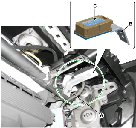
3.Remove the connector.
4.Remove the bracket (B) and receiver (C) by loosening the nut (A).
Tightening torque :3.9 - 5.9 N.m (0.4 - 0.6 kgf.m, 2.9 - 4.3 lb-ft)
5.Install in the reverse order of removal.
6.Re-connect the battery, and then turn on the ignition.

• Firmly fasten the receiver connector until you hear a click.
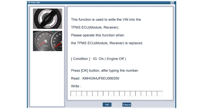
7.Replace the receiver, and then perform the learning process using a diagnostic instrument (GDS).
1.Connect the diagnostic instrument to the self-diagnostic connector (16-pin) beneath the crash pad on the side of driver's seat, and then turn on the ignition to activate the diagnostic instrument.
2.In the GDS Vehicle Type Selection menu, select "Vehicle Type" and "TPMS" System, and then opt for "OK."


Other information:
Hyundai Accent (HC) (2017 - 2022) Service Manual: Exterior Care
NOTICE If you park your Hyundai Accent near a stainless steel sign or glass facade building, the vehicle's exterior plastic parts such as a bumper, spoiler, garnish, lamp or outside rearview mirror might be damaged due to sunlight reflected from the sign or building. To prevent damage of the exterior plastic parts, you should avoid parking in areas where light may be reflected or use a car cover.Hyundai Accent (HC) (2017 - 2022) Service Manual: Occupant Classification System (OCS)
Your Hyundai Accent is equipped with an Occupant Classification System (OCS) in the front passenger’s seat. This smart safety feature works with the Hyundai Accent Supplemental Restraint System (SRS) to help manage front passenger air bag operation based on who—or what—is detected on the passenger seat. Main components of the Occupant Classification System A detection device located within the front passenger seat cushion that measures occupant presence and seating load.
Contents
- Components and Components Location
- Schematic Diagrams
- Description and Operation
- TPMS Sensor
- TPMS Receiver
Categories
- Manuals Home
- Hyundai Accent Owners Manual
- Hyundai Accent Service Manual
- Questions & Answers
- Video Guides
- Useful Resources
- New on site
- Most important about car
- Privacy Policy

0.0072