
Hyundai Accent (HC): Body (Interior and Exterior) / Trunk Trim
Contents:
Repair procedures

• Put on gloves to prevent hand injuries.

• When removing with a flat - tip screwdriver or remover, wrap protective tape around the tools to prevent damage to components.
• When removing the interior trim pieces, use a plastic panel removal tool not to damage the surface.
• Take care not to bend or scratch the trim and panels.
1.Remove the rear seat cushion assembly.(Refer to Rear Seat - "Rear Seat Assembly")
2.Remove the rear seat back assembly.(Refer to Rear Seat - "Rear Seat Assembly")
3.Remove the rear door scuff trim.(Refer to Interior Trim - "Door Scuff Trim")
4.After loosening the mounting screws, then remove the luggage partition center trim (A).
5.Remove the luggage covering mat (B).
6.Using a screwdriver or remover, remove the rear transverse trim (C).
7.Remove the rear wheel house trim (D).
8.After loosening the mounting screws, then remove the luggage side trim (E).
9.To install, reverse the removal procedure.[Bench type]
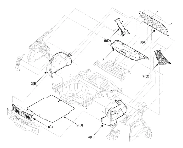
1. Rear transverse trim
2. Luggage covering mat
3. Luggage side trim [LH]
4. Luggage side trim [RH]
5. Rear package tray trim
6. Rear wheel house trim [LH]
7. Rear wheel house trim [RH]
8. Luggage partition center trim
[6:4 Folding type]
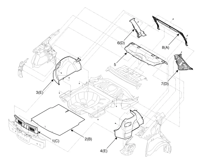
1. Rear transverse trim
2. Luggage covering mat
3. Luggage side trim [LH]
4. Luggage side trim [RH]
5. Rear package tray trim
6. Rear wheel house trim [LH]
7. Rear wheel house trim [RH]
8. Luggage partition center trim


Other information:
Hyundai Accent (HC) (2017 - 2022) Service Manual: Piston and Connecting Rod
- Disassembly • Use fender covers to avoid damaging painted surfaces. • To avoid damage, unplug the wiring connectors carefully while holding the connector portion. • Mark all wiring connector and hoses to avoid misconnection. • To release the fuel system pressure before removing the engine assembly, start the engine without fuel pump relay.Hyundai Accent (HC) (2017 - 2022) Service Manual: Stop Lamp Switch
- Components 1. Brake pedal member assembly2. Stop lamp switch3. Brake pedal arm 4. Pedal pad - Schematic Diagram - System circuit diagram - Terminal function TerminalDescription 1IGN 2BS 3- 4B+ 5BLS 6GND - Adjustment 1.Turn ignition switch OFF and disconnect the negative (-) battery cable. 2.Remove the lower crash pad.
Contents
Categories
- Manuals Home
- Hyundai Accent Owners Manual
- Hyundai Accent Service Manual
- Questions & Answers
- Video Guides
- Useful Resources
- New on site
- Most important about car
- Privacy Policy

0.0077