Hyundai Accent: Engine Mechanical System / Intake And Exhaust System
Air Cleaner
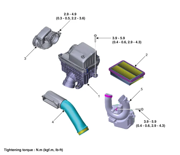
1. Air cleaner assembly
2. Air cleaner element
3. Air intake hose
4. Air duct
5. Resonator
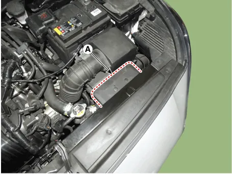
1.Disconnect the battery negative terminal.
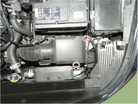
2.Remove the air duct (A).
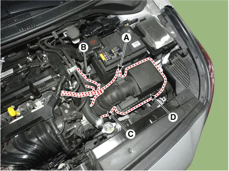
3.Remove the air cleaner assembly.
(1)Disconnect the air flow sensor (AFS) connector (A).
(2)Disconnect the breather hose B (B).
(3)Disconnect the intake air hose (C).
Tightening torque : 2.9 - 4.9 N.m (0.3 - 0.5 kgf.m, 2.2 - 3.6 lb-ft)
(4)Remove the air cleaner assembly (D).
Tightening torque : 3.9 - 5.9 N.m (0.4 - 0.6 kgf.m, 2.9 - 4.3 Ib-ft)
4.Install in the reverse order of removal.
1.Open the air cleaner cover by unhooking the clamps.
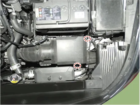
2. Replace the air cleaner element (A) with a new one.
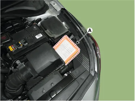

• If there are foreign substances inside the air cleaner assembly, wipe the inside of the air cleaner assembly and then replace the air cleaner element.
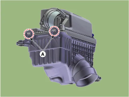
3.Close the air cleaner cover by hooking the clamps.

• Install the air cleaner cover, insert the hinge (A) and fill the clamp.
Intake Manifold
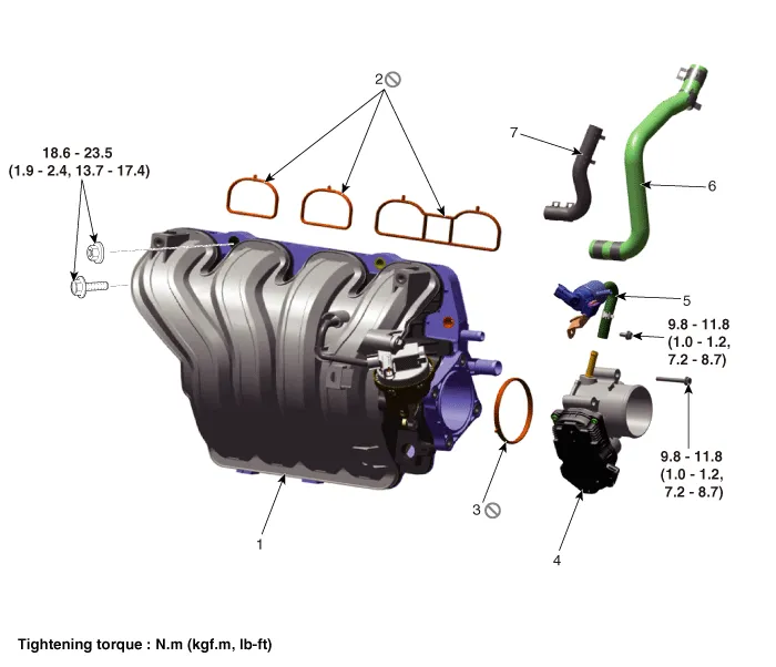
1. Intake manifold
2. Intake manifold gasket
3. Electronic throttle body (ETC) gasket
4. Electronic throttle body (ETC)
5. Purge control solenoid valve (PCSV) and hose
6. EGR hose
7. Vacuum hose
1.Disconnect the battery negative terminal.
2.Remove the engine cover.(Refer to Engine and Transaxle Assembly System - "Engine cover")
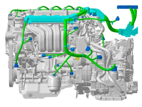
3.Remove the engine wire harness connectors and wire harness clamps from cylinder head and the intake manifold.
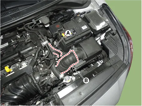
4.Disconnect the intake air hose.
(1)Disconnect the breather hose B (A).
(2)Disconnect the intake air hose (B).
Tightening torque : 2.9 - 4.9 N.m (0.3 - 0.5 kgf.m, 2.2 - 3.6 lb-ft)
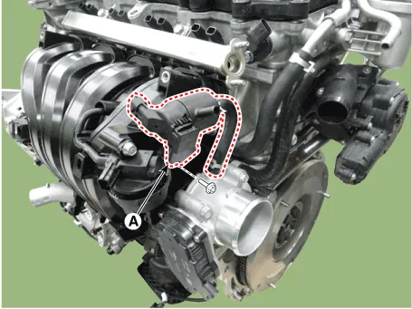
5.Remove the Purge control solenoid valve (PCSV) bracket (A) from intake manifold.
Tightening torque :9.8 - 11.8 N.m (1.0 - 1.2 kgf.m, 7.2 - 8.7 lb-ft)
6.Remove the Electronic Throttle Control (ETC) module.(Refer to Engine Control/ Fuel System - "ETC (Electronic Throttle Control")
7.Disconnect the vacuum hose (A) and EGR hose (B).
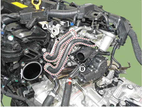
8.Remove the wiring bracket (A).
Tightening torque : 6.9 - 9.8 N.m (0.7 - 1.0 kgf.m, 5.1 - 13.7 lb-ft)
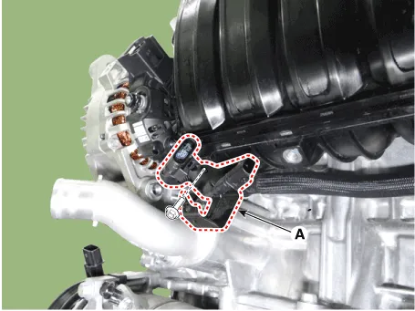
9.Remove the Intake Manifold (A).
Tightening torque : 18.6 - 23.5 N.m (1.9 - 2.4 kgf.m, 13.7 - 17.4 lb-ft)
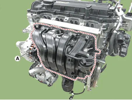
10.Install in the reverse order of removal.

• When installing, replace with new gaskets.
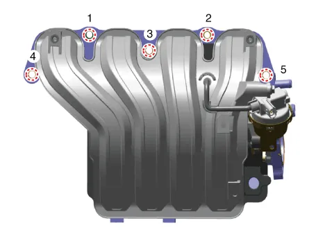
• When installing the intake manifold, tighten sequence shown.
Exhaust Manifold
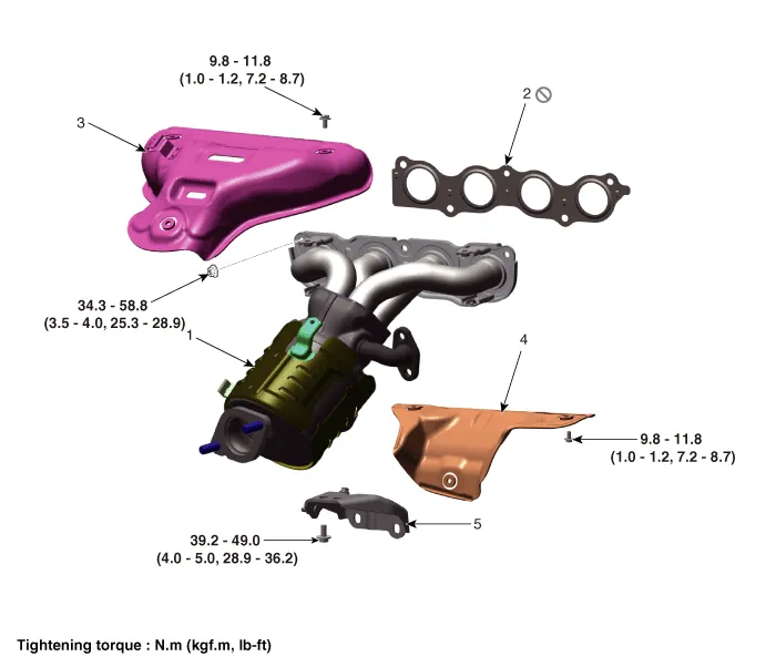
1. Exhaust manifold
2. Exhaust manifold gasket
3. Exhaust manifold heat protector A
4. Exhaust manifold heat protector B
5. Exhaust manifold stay
1.Disconnect the battery negative terminal.
2.Remove the engine cover.(Refer to Engine and Transaxle Assembly System - "Engine cover")
3.Remove the engine room under cover.(Refer to Engine and Transaxle Assembly System - "Engine Room Under Cover")
4.Disconnect the front oxygen sensor connectors (A).
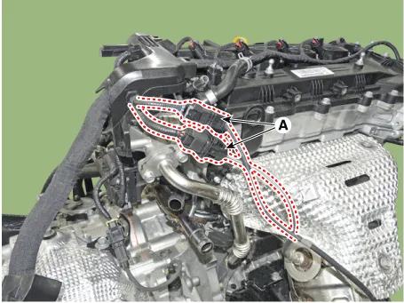
5.Remove the front muffler. (Refer to Intake and Exhaust Manifold - "Front Muffler")
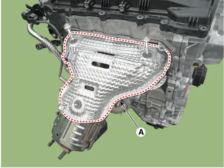
6.Remove the exhaust manifold heat protector A (A).
Tightening torque : 9.8 - 11.8 N.m (1.0 - 1.2 kgf.m, 7.2 - 8.7 lb-ft)
7.Remove the EGR cooler mounting nuts (A).
Tightening torque :18.6 - 23.5 N.m (1.9 - 2.4 kgf.m, 13.7 - 17.4 lb-ft)
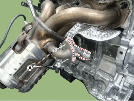
8.Remove the exhaust manifold stay (A).
Tightening torque :39.2 - 49.0 N.m (4.0 - 5.0 kgf.m, 28.9 - 36.2 lb-ft)
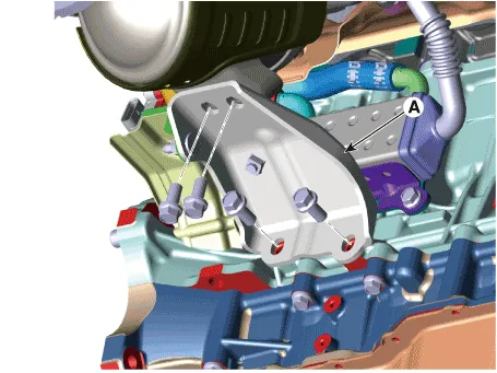
9.Remove the engine mounting support bracket.(Refer to Engine and Transaxle Assembly - "Engine Mounting")
10.With the jack, lower the engine to get enough space for removing the exhaust manifold.
11.Remove the exhaust manifold (A).
Tightening torque :34.3 - 39.2 N.m (3.5 - 4.0 kgf.m, 25.3 - 28.9 lb-ft)
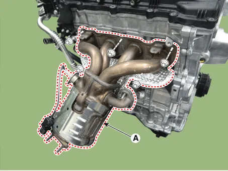
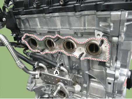
12.Remove the exhaust manifold gasket (A).
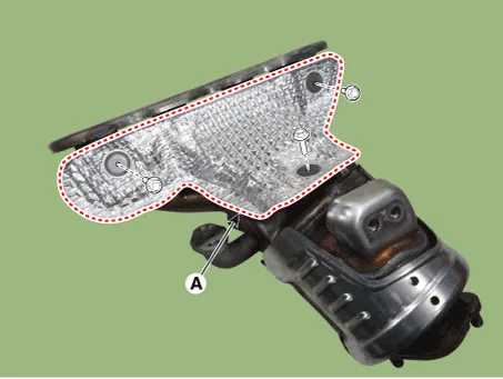
13.Remove the exhaust manifold heat protector B (A).
Tightening torque :9.8 - 11.8 N.m (1.0 - 1.2 kgf.m, 7.2 - 8.7 lb-ft)
14.Install in the reverse order of removal.

• When installing the exhaust manifold, with a new gasket.
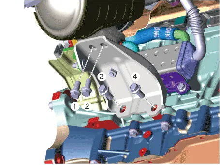
• When installing the exhaust manifold, tighten the nuts with pre-torque first and then tighten the nuts with specified torque in the sequence shown.
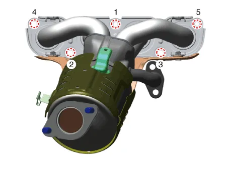
• When installing the exhaust manifold stay, tighten the nuts with pre-torque first and then tighten the nuts with specified torque in the sequence shown.
EGR Cooler
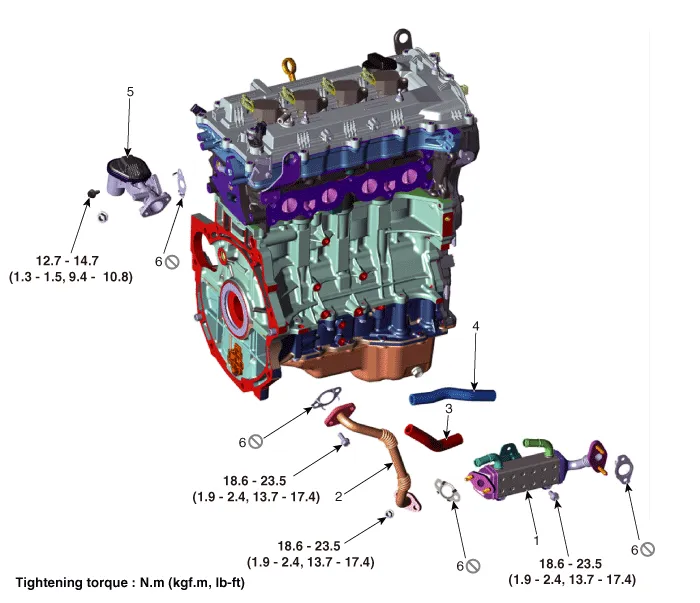
1. EGR cooler
2. EGR cooler pipe B
3. EGR cooler outlet hose
4. EGR cooler inlet hose
5. EGR valve
6. Gasket
1.Disconnect the battery negative terminal.
2.Remove the engine cover.(Refer to Engine and Transaxle Assembly - "Engine Cover")
3.Remove the engine room under cover.(Refer to Engine and Transaxle Assembly - "Engine Room Under Cover")
4.Loosen the drain plug and drain the coolant. (Refer to Cooling System - "Coolant")
5.Remove the exhaust manifold.(Refer to Intake And Exhaust System - "Exhaust Manifold")
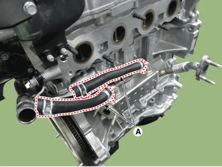
6.Disconnect the EGR cooler inlet and outlet hoses (A).
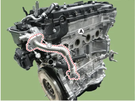
7.Remove the EGR cooler pipe B (A).
Tightening torque :18.6 - 23.5 N.m (1.9 - 2.4 kgf.m, 13.7 - 17.4 lb-ft)
8.Remove the EGR cooler (A).
Tightening torque :18.6 - 23.5 N.m (1.9 - 2.4 kgf.m, 13.7 - 17.4 lb-ft)
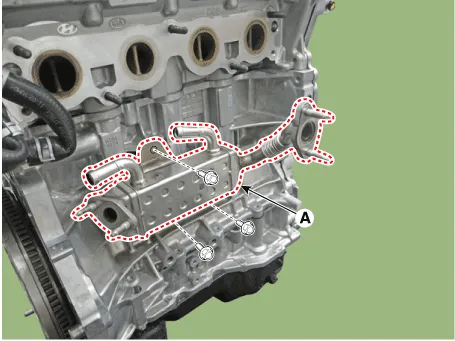
9.Install in the reverse order of removal.

• When installing, replace with new gaskets.
• When installing the EGR cooler, tighten the sequence shown.
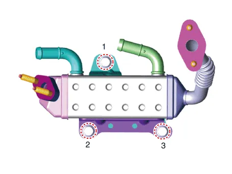
10.Fill the radiator with coolant.(Refer to Cooling system - "Coolant")

• The coolant must be injected according to the integrated thermal management module (ITM) coolant filling method.
Muffler ➤
Other information:
Hyundai Accent (HC) (2017 - 2022) Service Manual: Repair procedures
- Removal 1.Remove the air cleaner assembly.(Refer to Engine Mechanical System - "Air cleaner") 2.Remove the battery and battery tray.(Refer to Body Electrical System - "Battery") 3.Drain the coolant.(Refer to Engine Mechanical System - "Coolant") 4.Disconnect the position switch connector (A). 5.Disconnect the driven pully speed sensor connector (B).Hyundai Accent (HC) (2017 - 2022) Service Manual: Stop Lamp Switch
- Components 1. Brake pedal member assembly2. Stop lamp switch3. Brake pedal arm 4. Pedal pad - Schematic Diagram - System circuit diagram - Terminal function TerminalDescription 1IGN 2BS 3- 4B+ 5BLS 6GND - Adjustment 1.Turn ignition switch OFF and disconnect the negative (-) battery cable. 2.Remove the lower crash pad.
Contents
Categories
- Manuals Home
- Hyundai Accent Owners Manual
- Hyundai Accent Service Manual
- New on site
- Most important about car


