Hyundai Accent (HC): Body Electrical System / Auto Lighting Control System
Contents:
- Specifications
- Components and Components Location
- Schematic Diagrams
- Auto Light Switch
- Auto Light Sensor
Specifications
| Items | Specifications | |
| Rated voltage | 5V | |
| Load | Max. 1mA (When head lamp lighting) | |
| Illuminations (LUX) | 50 | 1.42 ± 0.31V |
| 100 | 2.63 ± 0.58V | |
| 150 | 3.84 ± 0.84V | |
Components and Components Location
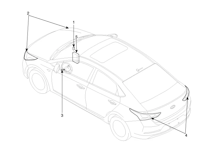
1. Auto light sensor
2. Head lamps
3. Lighting switch (Auto)
4. Tail lamps
5. BCM (Body Control Module)
Schematic Diagrams
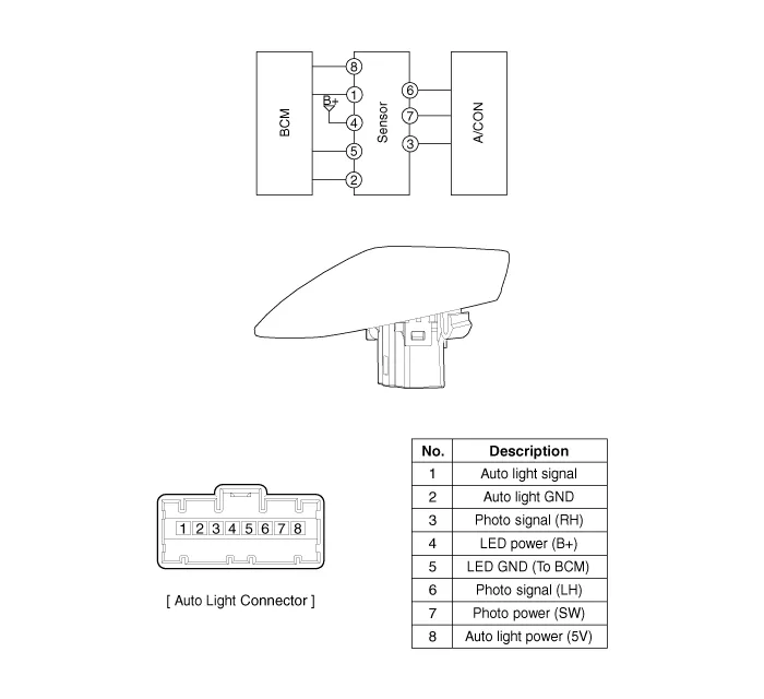
Auto Light Switch
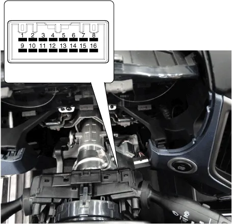
1.Oprate the auto light swith, then check for continuity between terminals of multi-function switch connector.
| Switch Position | SwitcH Terminal | Resistance (Ω, ±3.5%) |
| OFF | 9-14 | 680 |
| AUTO / DRL | ∞ | |
| Tail lamp | 1680 | |
| Low beam | 1680 |
Auto Light Sensor
1.Disconnect the negative (-) battery terminal.
2.Remove the photo & auto light sensor (A) from crash pad upper side by using screw (-) driver.
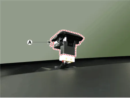
3.Remove the auto light connector.
1.Reconnect the auto light connector.
2.Install the auto light sensor.


Other information:

Contents
- Specifications
- Components and Components Location
- Schematic Diagrams
- Auto Light Switch
- Auto Light Sensor
Categories
- Manuals Home
- Hyundai Accent Owners Manual
- Hyundai Accent Service Manual
- Questions & Answers
- Video Guides
- Useful Resources
- New on site
- Most important about car
- Privacy Policy

0.004