Hyundai Accent (HC): Brake System (ABS/ESC) / Brake System
Contents:
- Repair procedures
- Brake Booster
- Master Cylinder
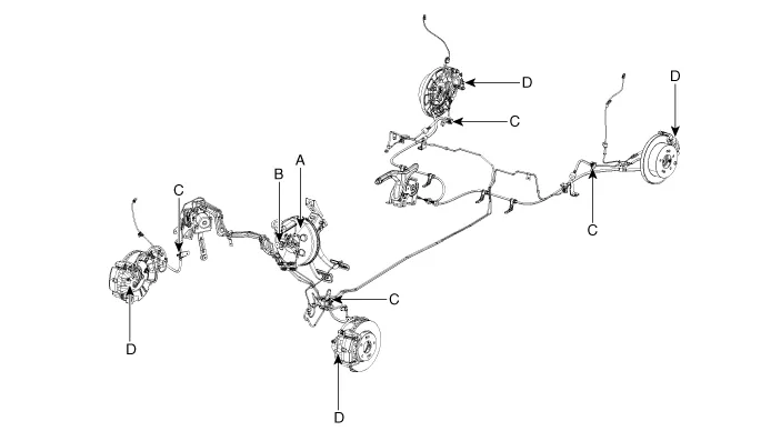
- Brake Line
- Brake Oil
- Brake Pedal
- Front Disc Brake
- Rear Disc Brake
- Rear Drum Brake
- Stop Lamp Switch
Repair procedures
| Component | Procedure | ||||
| Brake Booster (A) | Check brake operation by applying the brakes during a test drive. If the brakes do not work properly, check the brake booster. Replace the brake booster as an assembly if it does not work properly or if there are signs of leakage. | ||||
| Piston cup and pressure cup inspection (B) |
| ||||
| Brake hoses (C) | Look for damage or signs of fluid leakage. Replace the brake hose with a new one if it is damaged or leaking. | ||||
| Caliper piston seal and piston boots (D) | Check brake operation by applying the brakes. Look for damage or signs of fluid leakage. If the pedal does not work properly, the brakes drag, or there is damage or signs of fluid leakage, disassemble and inspect the brake caliper. Replace the boots and seals with new ones whenever the brake caliper is disassembled. |
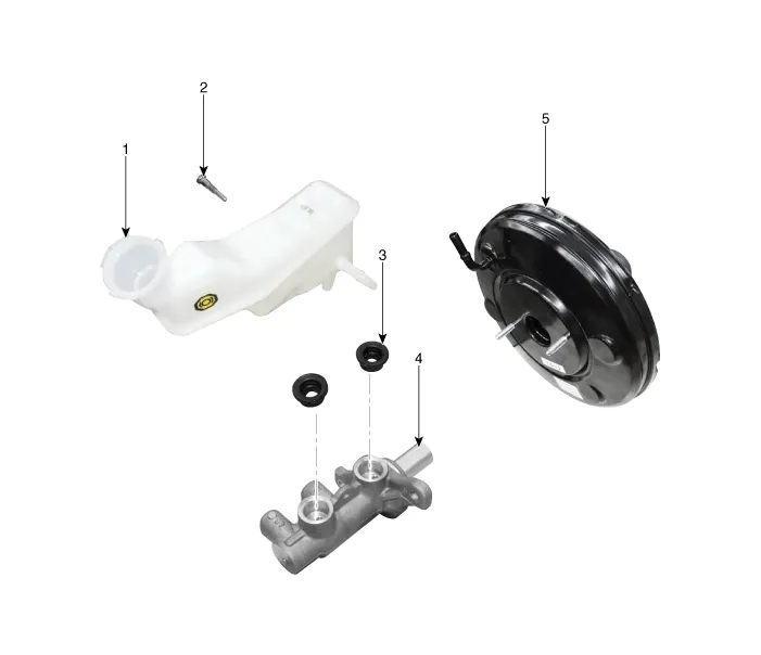
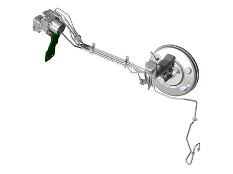
Brake Booster

1. Reservoir
2. Reservoir pin
3. Grommet
4. Master cylinder
5. Booster
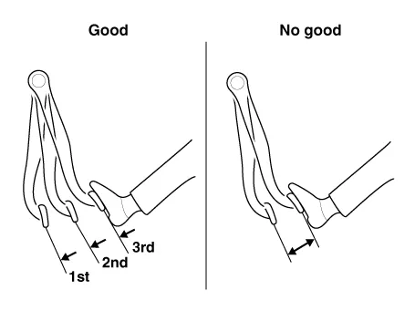
1.Run the engine for one or two minutes, and then stop it. If the pedal depresses fully the first time but gradually becomes higher when depressed succeeding times, the booster is operating properly, if the pedal height remains unchanged, the booster is inoperative.
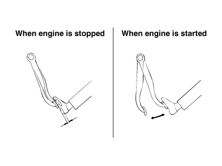
2.With the engine stopped, step on the brake pedal several times.Then step on the brake pedal and start the engine. If the pedal moves downward slightly, the booster is in good condition. If there is no change, the booster is inoperative.
3.With the engine running, step on the brake pedal and then stop the engine.Hold the pedal depressed for 30 seconds. If the pedal height does not change, the booster is in good condition, if the pedal rises, the booster is inoperative.If the above three tests are okay, the booster performance can be determined as good.Even if one of the above three tests is not okay, check the check valve, vacuum hose and booster for malfunction.
1.Turn ignition switch OFF and disconnect the negative (-) battery cable.
2.Remove the battery.(Refer to Engine Electrical System - "Battery")
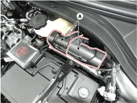
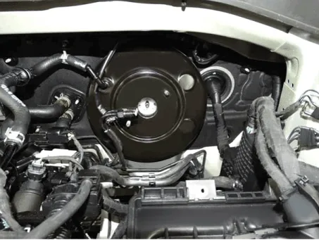
3.Remove the ECM (A).
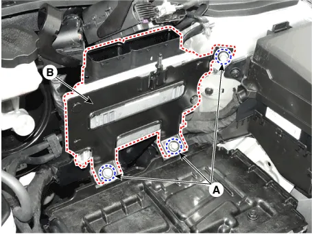
4.Loosen the mounting bolts (A) and then remova the ECM bracket (B).
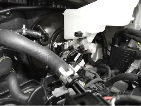
5.Disconnect the brake fluid level switch connector.
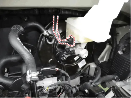
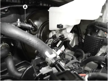
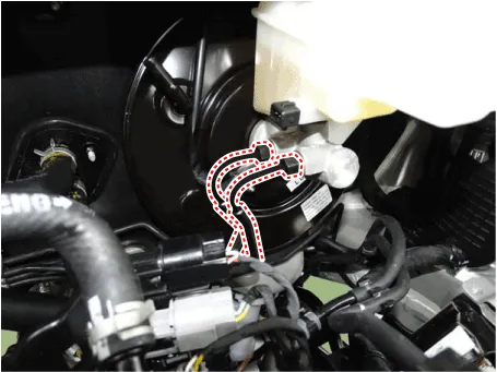
6.Remove the vacuum hose (A).
7.Remove the brake fluid from the master cylinder reservoir with a syringe.

• Do not spill brake fluid on the vehicle, it may damage the paint; if brake fluid does contact the paint, wash it off immediately with water.
8.Remove the master cylinder. (Refer to Brake System - "Master Cylinder")
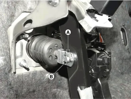
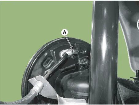
9.Remove the snap pin (A) and clevis pin (B).
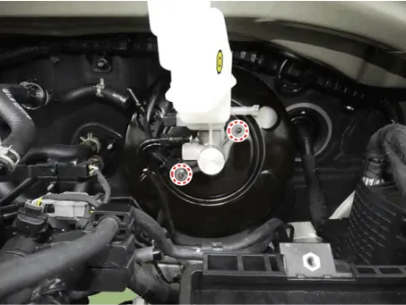
10.Remove the mounting nuts.
Tightening torque :16.7 - 25.5 N.m (1.7 - 2.6 kgf.m, 12.3 - 18.8 lb-ft)
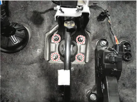
11.Remove the brake booster.
1.Inspect the vacuum hose.
2.Check the boot for damage.
1.To install, reverse the removal procedure.

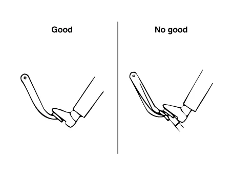
• Before installing the pin, apply the grease to the joint pin.
• Use a new snap pin whenever installing.
2.After installing, bleed the brake system. (Refer to Brake System - "Brake System Bleeding")(Refer to Brake System - "ABS System Bleeding")(Refer to Brake System - "ESP System Bleeding")
Master Cylinder
1. Reservoir
2. Reservoir pin
3. Grommet
4. Master cylinder
5. Booster
1.Turn ignition switch OFF and disconnect the negative (-) battery cable.
2.Disconnect the brake fluid level switch connector.

3.Remove the brake fluid from the master cylinder reservoir with a syringe.

• Do not spill brake fluid on the vehicle, it may damage the paint; if brake fluid does contact the paint, wash it off immediately with water.
4.Disconnect the brake tube from the master cylinder after loosening the tube flare nut.
Tightening torqueESP : 18.6 - 22.6 N.m (1.9 - 2.3 kgf.m, 13.7 - 16.6 lb-ft)ABS : 13.7 - 16.7 N.m (1.4 - 1.7 kgf.m, 10.1 - 12.3 lb-ft)
5.Remove the master cylinder from the brake booster after loosening the mounting nuts.
Tightening torque :9.8 - 15.9 N.m (1.0 - 1.6 kgf.m, 7.2 - 11.6 lb-ft)

6.Remove the reservoir by loosening the screw.
1.To install, reverse the removal procedure.
2.After installing, bleed the brake system. (Refer to Brake System - "Brake System Bleeding")(Refer to Brake System - "ABS System Bleeding")(Refer to Brake System - "ESP System Bleeding")
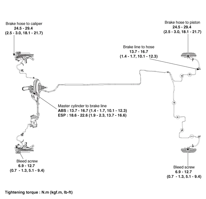
Brake Line
[Disc Type]
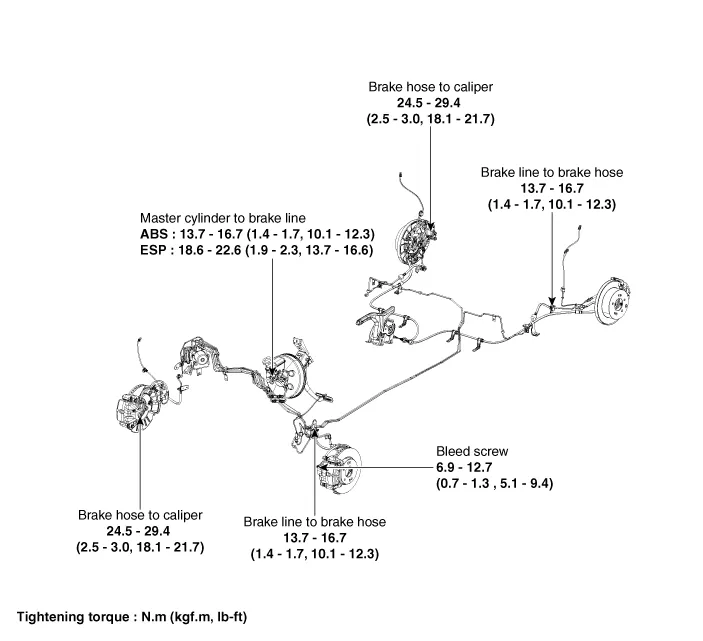
[Drum Type]
1.Disconnect the negative (-) battery cable.
2.Disconnect the brake fluid level switch connector.

3.Remove the brake fluid from the master cylinder reservior with a syringe.

• Do not spill brake fluid on the vehicle, it may damage the paint; if brake fluid does contact the paint, wash it off immediately with water.
4.Remove the brake tube from the ESP (ABS), master cylinder and brake tube connector.
Tightening torqueABS : 13.7 - 16.7 N.m (1.4 - 1.7 kgf.m, 10.1 - 12.3 lb-ft)ESP : 18.6 - 22.6 N.m (1.9 - 2.3 kgf.m. 13.7 - 16.6 lb-ft)Brake tube connector : 13.7 - 16.7 N.m (1.4 - 1.7 kgf.m, 10.1 - 12.3 lb-ft)Master cylinder : 13.7 - 16.7 N.m (1.4 - 1.7 kgf.m, 10.1 - 12.3 lb-ft)

• When replacing, be careful not to damage the brake tube.
1.Disconnect the negative (-) battery cable.
2.Disconnect the brake fluid level switch connector.

3.Remove the brake fluid from the master cylinder reservior with a syringe.

• Do not spill brake fluid on the vehicle, it may damage the paint; if brake fluid does contact the paint, wash it off immediately with water.
4.Remove the wheel & tire.
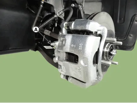
5.Remove the brake hose clip (A).
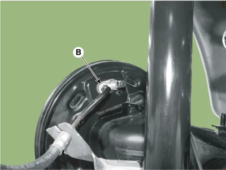
6.Disconnect the brake tube by loosening the tube flare nut (B).
Tightening torque :12.7 - 16.7 N.m (1.3 - 1.7 kgf.m, 9.4 - 12.3 lb-ft)
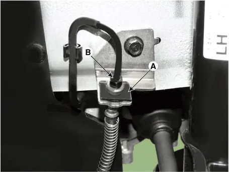
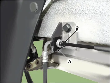
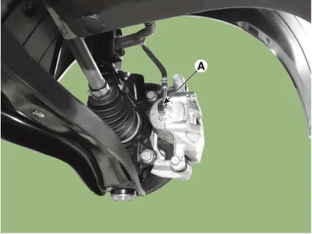
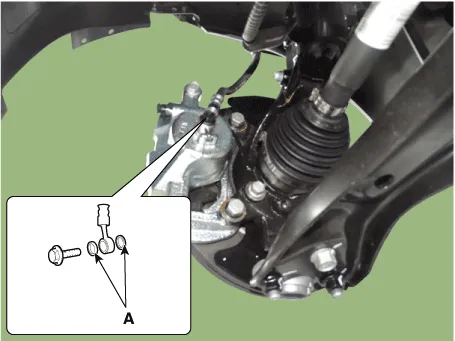
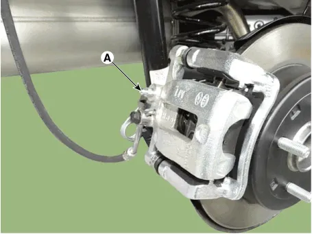
7.Disconnect the brake hose by loosening the bolt (A) & (B).
Tightening torque :24.5 - 29.4 N.m (2.5 - 3.0 kgf.m, 18.1 - 21.7 lb-ft)

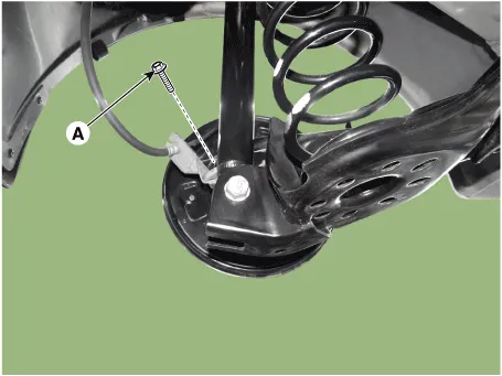
8.Remove the brake hose bracket by loosening the bolt (A). [Drum brake only]
Tightening torque :18.6 - 25.5 N.m (1.9 - 2.6 kgf.m, 13.7 - 18.8 lb-ft)
1.Check the brake tubes for cracks, crimps and corrosion.
2.Check the brake hoses for cracks, damage and fluid leakage.
3.Check the brake tube flare nuts for damage and fluid leakage.
4.Check brake hose mounting bracket for crack or deformation.
1.To install, reverse the removal procedure.

• Use a new washer (A) whenever installing.
2.After installing, bleed the brake system. (Refer to Brake System - "Brake System Bleeding")(Refer to Brake System - "ABS System Bleeding")(Refer to Brake System - "ESP System Bleeding")
3.Check the spilled brake oil.
Brake Oil
Brake oil : DOT 3 or DOT 4
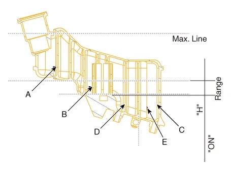
| Reservoir capacity (cc) | ||
| MAX LEVEL | A + B + C + D + E | 409 ± 20 |
| ON LEVEL (MIN LEVEL) (H = 23 ± 1.5 mm) | B + C + D | 138 ± 10 |
| PARTIAL LEVEL | C (PRI) | 28 |
| D (SEC) | 31 | |
| CLUTCH LEVEL | E | 12 |
1.Disconnect the battery (-) terminal.
2.Remove the brake fluid level sensor connector.

3.Remove the reservoir cap and remove the brake fluid from the reservoir tank using the cleaner.

• Be careful so that the brake fluid may not come in contact with the vehicle or human body. If it did, wipe out immediately.
• Make sure to remove any foreign substances around the reservoir and the reservoir cap before opening the reservoir cap.
4.Loosen the bleed screw (A) and have an assistant press the brake
pedal several times to remove any remaining brake fluid from the brake
tube.


• The steps should be performed in the order of rear right, front left, rear left and front right.
• Be careful so that the brake fluid may not come in contact with the vehicle or human body. If it did, wipe out immediately.
5.Loosen the bleed screw (A) and have an assistant press the brake
pedal several times to remove any remaining brake fluid from the brake
tube.


• The steps should be performed in the order of rear right, front left, rear left and front right.
• Be careful so that the brake fluid may not come in contact with the vehicle or human body. If it did, wipe out immediately.
6.Tighten the bleed screw and fill up to the 'MAX' line of the reservoir with the brake fluid.
7.Connect the battery (-) terminal.
8.Connect the brake fluid level sensor connector.

9.Loosen the bleed screw (A) and have an assistant press the brake
pedal several times until the brake fluid reaches the caliper cylinder.


• The steps should be performed in the order of rear right, front left, rear left and front right.
• Be careful so that the brake fluid may not come in contact with the vehicle or human body. If it did, wipe out immediately.
• Make sure the brake fluid of the reservoir tank does not go below the MIN level.
10.Tighten the bleed screw.
11.Have an assistant press the brake pedal several times to pressurize it and keep it pressed.
12.While the assistant is pressing down on the brake pedal, loosen the bleed screw to remove air and quickly tighten it again.

• The steps should be performed in the order of rear right, front left, rear left and front right.
• Be careful so that the brake fluid may not come in contact with the vehicle or human body. If it did, wipe out immediately.
• Make sure the brake fluid of the reservoir tank does not go below the MIN level.
13.Repeat the above steps until all bubbles are completely removed.
Brake Pedal
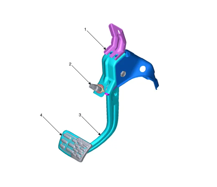
1. Brake pedal member assembly
2. Stop lamp switch
3. Brake pedal arm
4. Pedal pad
1.Turn ignition switch OFF and disconnect the negative (-) battery cable.
2.Remove the crash pad lower panel.(Refer to Body - "Crash Pad")
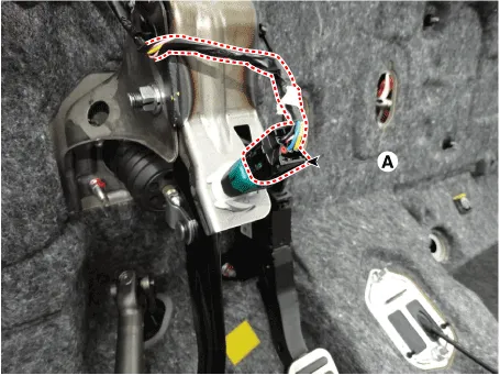
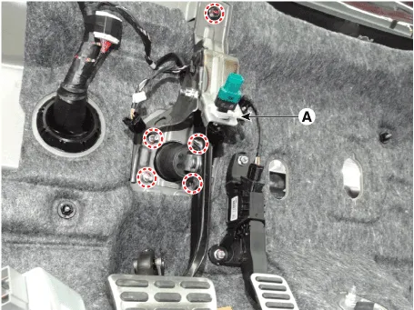
3.Disconnect the stop lamp switch connector (A).
4.Remove the snap pin (A) and clevis pin (B).
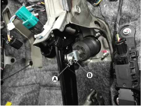
5.Remove the brake pedal assembly (A) after loosening the bolt and nut.
Tightening torque :16.7 - 25.5 N.m (1.7 - 2.6 kgf.m, 12.3 - 18.8 lb-ft)
1.Check the brake pedal for bending or twisting.
2.Check the brake pedal return spring for damage.
3.Check the stop lamp switch.
Front Disc Brake ➤
Rear Disc Brake ➤
Rear Drum Brake

1. Shoe hold down pin
2. Shoe adjuster
3. Upper return spring
4. Adjusting lever
5. Shoe
6. Adjusting spring
7. Lower return spring
8. Shoe hold spring
1.Loosen the wheel nuts slightly. Raise the vehicle, and make sure it is securely supported.
2.Remove the rear wheel and tire (A).
Tightening torque :107.9 - 127.5 N.m (11.0 - 13.0 kgf.m, 79.6 - 94.0 lb-ft)
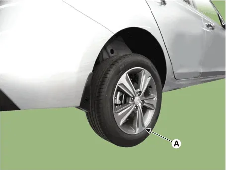

• Be careful not to damage the hub bolts when removing the rear wheel and tire.
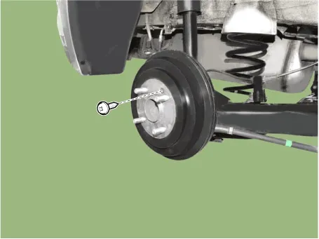
3.Loosen the screw and then remove the drum.
Tightening torque :4.9 - 5.9 N.m (0.5 - 0.6 kgf.m, 3.6 - 4.3 lb-ft)
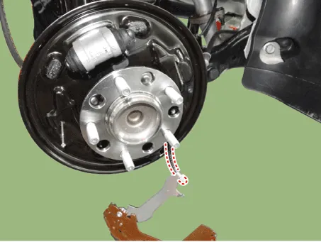
4.Remove the upper shoe return spring (A), lower shoe return spring (B), level pawl (C) and djuster assembly (D).

5.Remove the adjusting spring (A).

6.Remove the shoe hold assembly (A) and then remove the brake shoe.

7.Disconnect the parking cable.
8.Disconnect the brake fluid tube flare nut (A).
Tightening torque :12.7 - 16.7 N.m (1.3 - 1.7 kgf.m, 9.4 - 12.3 lb-ft)

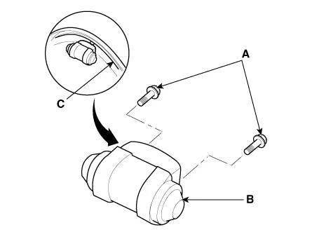
9.Loosen the mounting bolts (A) and then remove the wheel cylinder (B) from the backing plate (C).
10.Install in the reverse order of removal.
11.After installation, bleed the brake system. (Refer to Brake System - "Brake System Bleeding")(Refer to Brake System - "ESP System Bleeding")(Refer to Brake System - "ABS System Bleeding")

• Frequent inhalation of brake pad dust, regardless of material composition, could be hazardous to your health.
• Avoid breathing dust particles.
• Never use an air hose or brush to clean brake assemblies.

• Contaminated brake linings or drums reduce stopping ability.
• Block the front wheels before jacking up the rear of the vehicle.
1.Raise the rear of the vehicle, and make sure it is securely supported.
2.Release the parking brake, and remove the rear brake drum.
3.Check the wheel cylinder (A) for leakage.

4.Check the brake linings (B) for cracking, glazing, wear, and contamination.
5.Measure the brake lining thickness (C).Measurement does not include brake shoe thickness.
Brake lining thicknessStandard : 4.5 mm (0.177 in)Service limit : 1.0 mm (0.039 in)
6.If the brake lining thickness is less than the service limit, replace the brake shoes as a set.
7.Check the bearings in the hub unit for smooth operation. If it requires servicing, replace it.
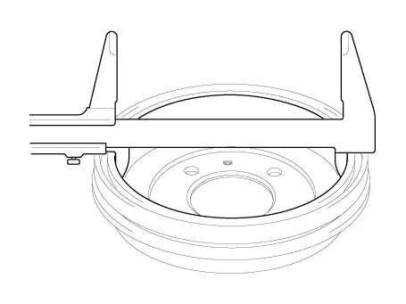
8.Measure the inside diameter of the brake drum with inside vernier calipers.
Drum inside diameterStandard : 205.3 mm (9.0 in)Service limit : 207.3 mm (9.08 in)Drum roundnessService limit : 0.06 mm (0.00236 in)
9.If the inside diameter of the brake drum is more than the service limit, replace the brake drum.
10.Check the brake drum for scoring, grooves, and cracks.
11.Inspect the brake lining and drum for proper contact.

12.Inspect the wheel cylinder outside for excessive wear and damage.
13.Inspect the backing plate for wear or damage.
Stop Lamp Switch ➤


Other information:
Hyundai Accent (HC) (2017 - 2022) Service Manual: General Safety Information and Caution
- Instructions • The R-1234yf liquid refrigerant is flammable gas. The gas reduces oxygen available for breathing and causes asphyxiation in high concentrations. The victim will not realize that he/she is suffocating. • Inhalation may cause central nervous system effects and may cause drowsiness and dizziness. • Ingestion may cause gastrointestinal discomfort.Hyundai Accent (HC) (2017 - 2022) Service Manual: Piston and Connecting Rod
- Disassembly • Use fender covers to avoid damaging painted surfaces. • To avoid damage, unplug the wiring connectors carefully while holding the connector portion. • Mark all wiring connector and hoses to avoid misconnection. • To release the fuel system pressure before removing the engine assembly, start the engine without fuel pump relay.
Contents
- Repair procedures
- Brake Booster
- Master Cylinder
- Brake Line
- Brake Oil
- Brake Pedal
- Front Disc Brake
- Rear Disc Brake
- Rear Drum Brake
- Stop Lamp Switch
Categories
- Manuals Home
- Hyundai Accent Owners Manual
- Hyundai Accent Service Manual
- Questions & Answers
- Video Guides
- Useful Resources
- New on site
- Most important about car
- Privacy Policy

0.0087