Hyundai Accent (HC): Engine Mechanical System / Cooling System
Contents:
- Troubleshooting
- Coolant
- Cooling Fan
- Radiator
- Integrated Thermal Management Module (ITM)
- Water Inlet Fitting
- Water pump
Troubleshooting
| Inspection | Remedy | |||||
| Visual inspection | Inspect for shortage of coolant in reservoir tank . | Reinspect after replenishing coolant. | ||||
| Inspect for coolant pollution after removing radiator cap. | Reinspect after replacing coolant. | |||||
|

Inspect for leakage and loose coolant hoses
(radiator hose, heater hose, oil cooler hose, etc.).
Reinspect for leakage after reinstalling hoses and clamps.
Checking for coolant leaks of Integrated Thermal Management Module (ITM)
Replace O-ring or replace the integrated thermal management module (ITM) if required
Inspecting the heater pipe connection to find coolant leaks.
Reinspect for leakage after reinstalling hoses and clamps.
Inspect for leakage on water inlet fitting mounting part.
Reinspect for leakage after replacing O-ring.
Reinspect for leakage after tightening to the specified torque.
Inspect drive belt (for normal operation of water pump).
Adjust drive belt tension or replace.
Inspect for leakage on water pump gasket mounting part.
Reinspect for leakage after replacing gasket.
Reinspect for leakage after tightening to the specified torque.
Inspect for loose coolant temperature sensor, cooling fan connector and pin.
Reinstall loose connector.
Replace relevant part if connector pin is damaged.
Inspect operation status of cooling fan.
- Check operation status by switching ON/OFF the heater control A/C.
Check mounting status of ground cable.

• Will not operate in cold ambient temperature.
Diagnostic device
Inspect self-diagnostic code using GDS.
Check coolant temperature sensor, wiring, connector, etc.
Unit inspection
Inspect water pump impeller.
Replace water pump.
Coolant

• Never remove the radiator cap when the engine is hot. Serious scalding could be caused by hot fluid under high pressure escaping from the radiator.

• When pouring engine coolant, be sure to shut the relay box lid and not to let coolant spill on the electrical parts or the paint. If any coolant spills, rinse it off immediately.
• When changing the coolant and draining air, be sure to follow the filling instructions of the Integrated Thermal Management Module (ITM).
1.Make sure the engine and radiator are cool to the touch.
2.Remove the radiator cap (A).
3.Remove the engine room under cover.(Refer to Engine and Transaxle Assembly - "Engine Room Under Cover")
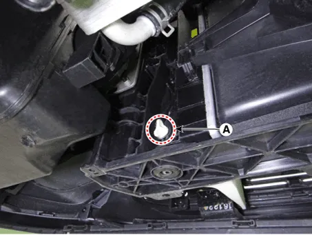
4.Loosen the drain plug (A), and drain the coolant.

5.Tighten the radiator drain plug securely after draining the coolant.
6.Remove the cooling fan assembly and after draining engine coolant in the reservoir tank, clean the reservoir tank. (Refer to Cooling System - "Cooling Fan")
7.Install the cooling fan assembly. (Refer to Cooling System - "Cooling Fan")
8.Fill with fluid mixture of coolant and water (45 - 60%) slowly through the radiator cap.

• Make sure to insert the maximum amount of coolant after turning off the engine and cutting the power of the components.
Coolant capacityMT : Approx. 6.4L(1.69 US.gal., 6.76 US,qt., 5.63lmp.qt.)IVT : Approx. 6.6L(1.74 US.gal., 6.97 US,qt., 5.80 Imp.qt.)

• Press the upper / lower hoses on the radiator so that the air can get out easily.
• Use only genuine antifreeze/coolant.
• For best corrosion protection, the coolant concentration must be maintained year-round at 45 - 60% minimum.Coolant concentrations less than 45 - 60% may not provide sufficient protection against corrosion or freezing.
• Coolant concentrations greater than 60% will impair cooling efficiency and are not recommended.
• Do not mix different brands of antifreeze/coolants.
• Do not use additional rust inhibitors or antirust products; they may not be compatible with the coolant.
9.Start the engine.

• Keep the engine idle.
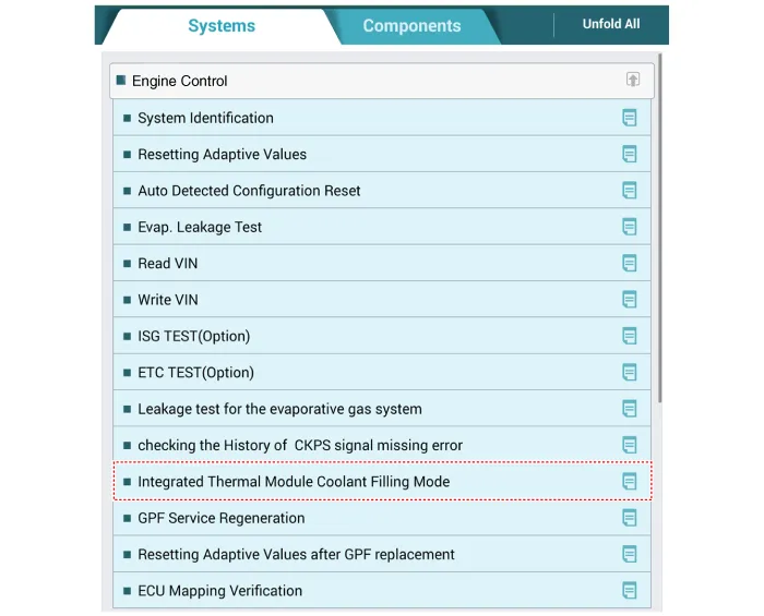
10.Connect the GDS.
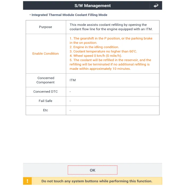
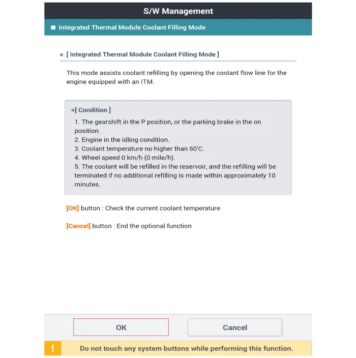
11.Use the GDS to activate the "integrated thermal management module (ITM) coolant refill mode".
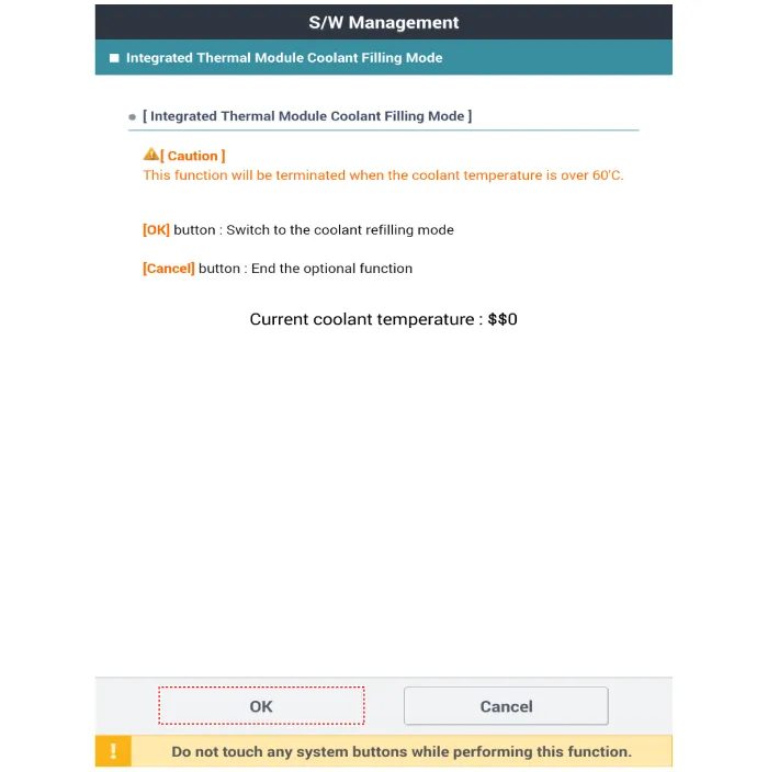
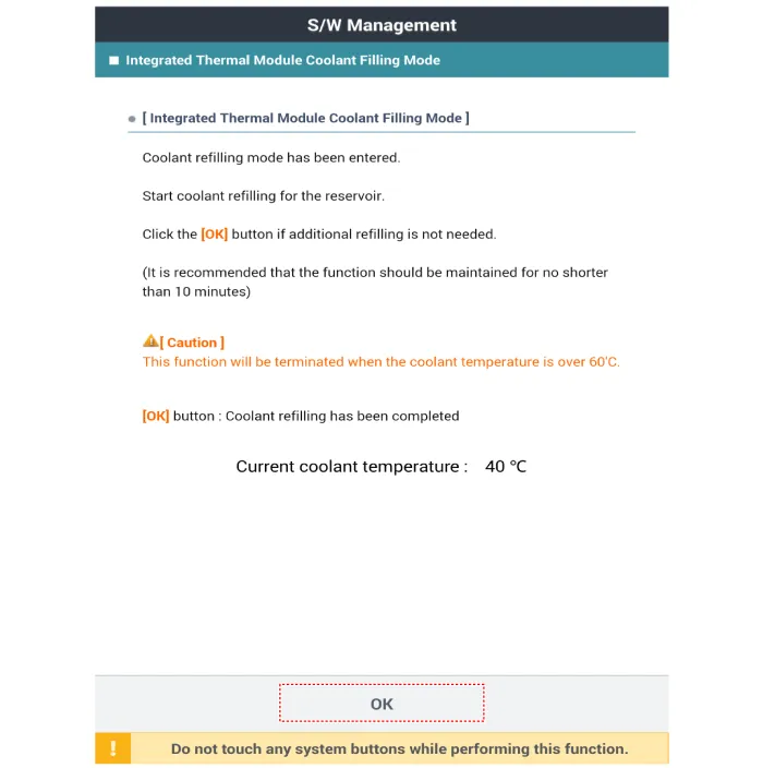
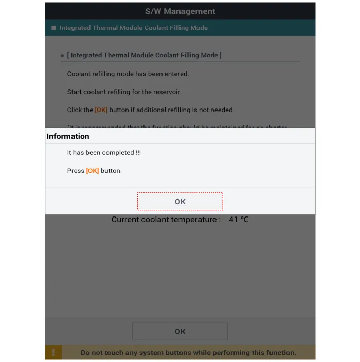
12.After the cooling fan operates once, warm up the engine for 20 minutes.
13.Disconnect the GDS, and then restart the engine after turning the engine OFF.
14.Install the radiator cap (A).

15.Check the coolant quantity after driving the vehicle.
16.If the coolant is insufficient, replenish it.
17.Install the engineroom under cover.(Refer to Engine and Transaxle Assembly - "Engine Room Under Cover")
1.Make sure the engine and radiator are cool to the touch.
2.Remove the radiator cap (A).

3.Remove the engine room under cover.(Refer to Engine and Transaxle Assembly - "Engine Room Under Cover")
4.Loosen the drain plug (A), and drain the coolant.
5.Tighten the radiator drain plug securely after draining the coolant.
6.Remove the cooling fan assembly and after draining engine coolant in the reservoir tank, clean the tank. (Refer to Cooling System - "Cooling Fan")
7.Install the cooling fan assembly. (Refer to Cooling System - "Cooling Fan")
8.Fill with fluid mixture of coolant and water (45 - 60%) slowly through the radiator cap.

• Make sure to insert the maximum amount of coolant after turning off the engine and cutting the power of the components.
Coolant capacityMT : Approx. 6.4L(1.69 US.gal., 6.76 US,qt., 5.63lmp.qt.)IVT : Approx. 6.6L(1.74 US.gal., 6.97 US,qt., 5.80 Imp.qt.)

• Press the upper / lower hoses on the radiator so that the air can get out easily.
• Use only genuine antifreeze/coolant.
• For best corrosion protection, the coolant concentration must be maintained year-round at 45 - 60% minimum.Coolant concentrations less than 45 - 60% may not provide sufficient protection against corrosion or freezing.
• Coolant concentrations greater than 60% will impair cooling efficiency and are not recommended.
• Do not mix different brands of antifreeze/coolants.
• Do not use additional rust inhibitors or antirust products; they may not be compatible with the coolant.
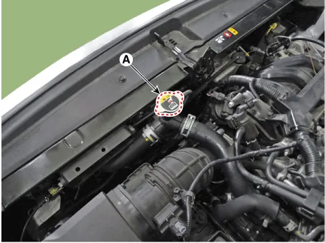
9.Disconnect the integrated thermal management module (ITM) connector (A).


• When disconnecting the integrated thermal management module (ITM) connector, make sure that there is no power to the engine and other components.
• Be careful that static electricity and other voltages are not applied to the integrated thermal management module (ITM).
• Do not bring anything with magnetism, such as a magnet, close to the integrated thermal management module (ITM).
10.Start the engine.

• Keep the engine idle.
11.After the cooling fan operates once, warm up the engine for 20 minutes.
12.After shut engine off and connect the integrated thermal management module (ITM) connector (A).
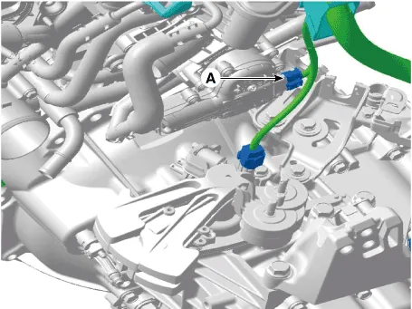

• When connecting the integrated thermal management module (ITM) connector, water or oil must be completely removed from the connector and no foreign matters should be entered.
• When replacing the integrated thermal management module (ITM) connector, be sure to use the specified connector.
13.Start the engine.
14.Check whether the integrated thermal management module (ITM) is working by listening to the operating sound.

• The operation sound of the integrated thermal management module (ITM) may occur before or after the engine start.
15.Check the coolant quantity after driving the vehicle.
16.If the coolant is insufficient, replenish it.
17.Install the engineroom under cover.(Refer to Engine and Transaxle Assembly - "Engine Room Under Cover")
Cooling Fan
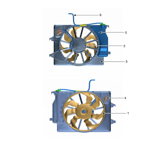
1. Cooling fan
2. Fan motor
3. Cooling fan shroud
4. Resister
5. Reservoir tank
6. Over flow hose
1.Disconnect the battery negative terminal.
2.Remove the air duct.(Refer to Intake and Exhaust System - "Air Cleaner")
3.Remove the engine room under cover.(Refer to Engine and Transaxle Assembly - "Engine Room Under Cover")
4.Drain the coolant.(Refer to Cooling System - "Coolant")
5.Remove the front bumper.(Refer to Body (Interior and Exterior) - "Front Bumper")
6.Remove the horn.(Refer to Body Electrical System - "Horn")
7.Disconnect the wiring harness connector (A).
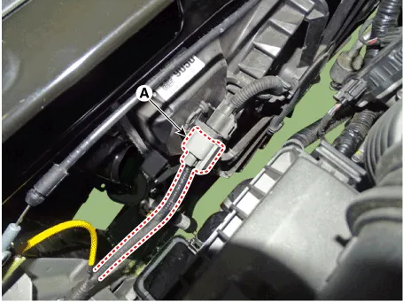
8.Disconnect the over flow hose (A).
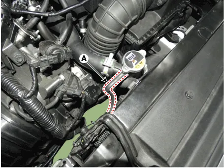
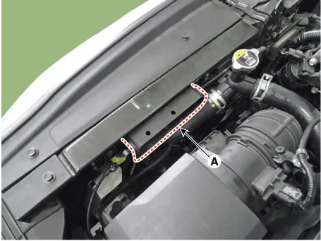
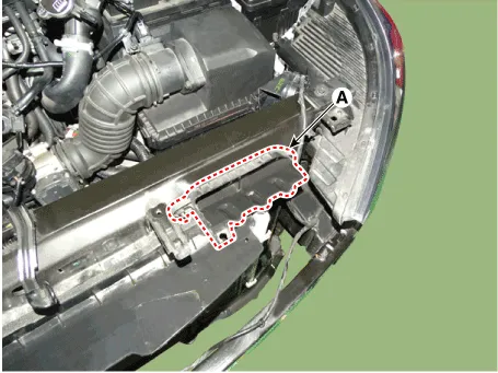
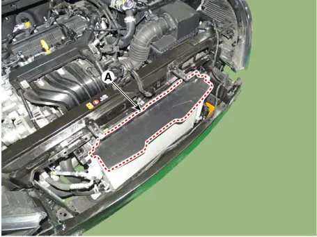
9.Remove the intake shield (A).
Tightening torque: 7.8 - 9.8 N.m (0.8 - 1.0 kgf.m , 5.8 - 7.2 lb-ft)
10.Disconnect the radiator upper hose (A).
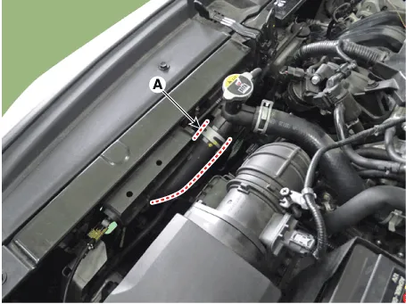
11.Remove the side air guard (A).
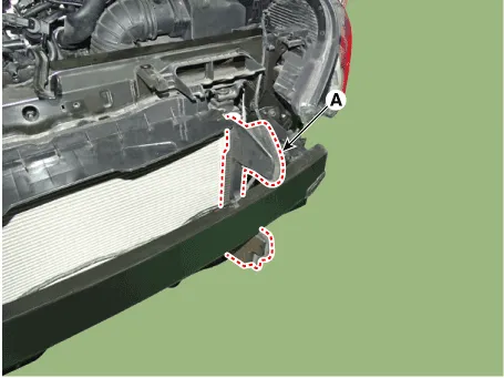
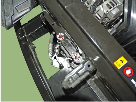
12.Remove the air intake shield (A).
Tightening torque: 7.8 - 11.8 N.m (0.8 - 1.2 kgf.m, 5.8 - 8.7 lb-ft)
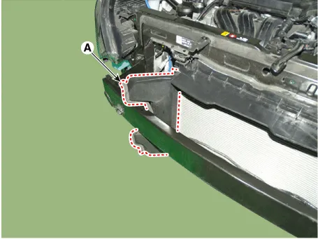
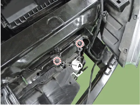
13.Remove the radiator mounting bracket bolts (A).
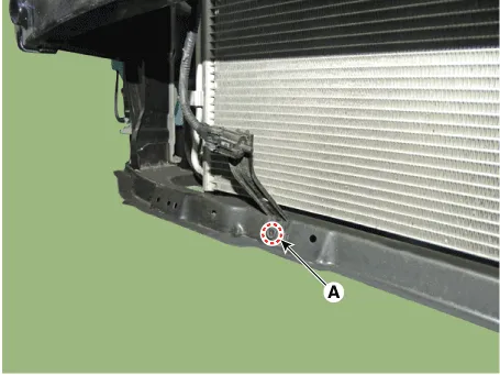
14.remove the ambient temperature sensor bracket mounting bolt (A).
15.Remove the upper air guard.
16.Separate the A/C condenser from the radiator assembly.
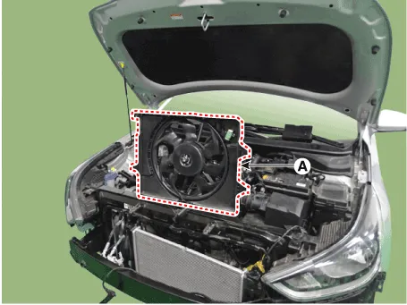
17.Remove the cooling fan assembly (A).
18.Install in the reverse order of removal.
19.Fill with engine coolant. (Refer to Cooling System - "Coolant")

• The coolant must be injected according to the integrated thermal management module (ITM) coolant filling method.
1.Disconnect the battery negative terminal.
2.Remove the air duct.(Refer to Intake and Exhaust System - "Air Cleaner")
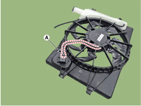
3.Disconnect the wiring harness connector (A) and cooling fan motor connector (B).
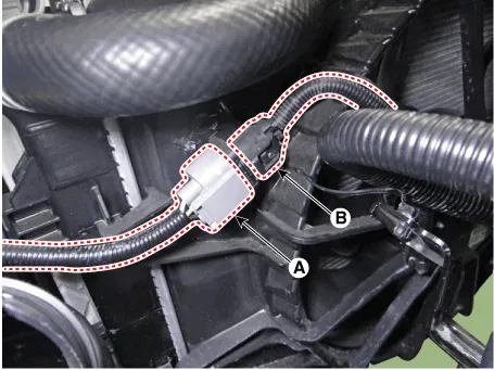
4.Remove the resistor (A).
Tightening torque :1.8 - 2.5 N.m (0.18 - 0.25 kgf.m, 1.3 - 1.8 lb-ft)
5.Install in the reverse order of removal.
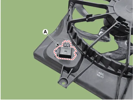
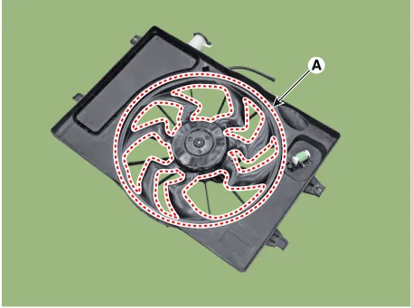
1.Disconnect the cooling fan motor connector (A).
2.Remove the cooling fan (A) from the cooling fan assembly.
Tightening torque :2.8 - 3.2 N.m (0.28 - 0.33 kgf.m, 2.0 - 2.4 lb-ft)
3.Remove the fan motor (A) from the cooling fan shroud.
Tightening torque :3.9 - 5.9 N.m (0.4 - 0.6 kgf.m, 2.9 - 4.3 lb-ft)
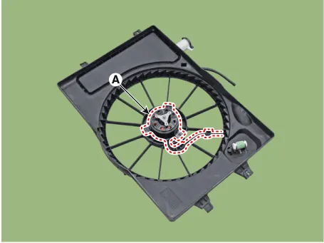
4.Install in the reverse order of removal.
1.Turn ignition switch "OFF" and connect the GDS to the Data Link Connector.
2.With the gear shift in P (Park) position and ignistion switch "ON" (LED of the Power button illuminates in Red), select the "force drive" function.
3.Force drive the cooling fan motor.
(1)Start the "Fan motor low speed" of the force drive function.
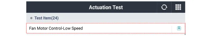
(2)Press the start button and force drive for 5 seconds.
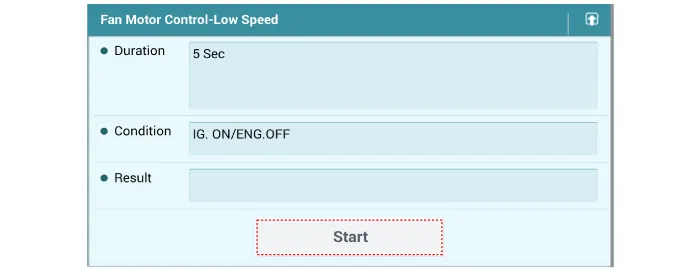
(3)Visually check the operation of the cooling fan.
Radiator
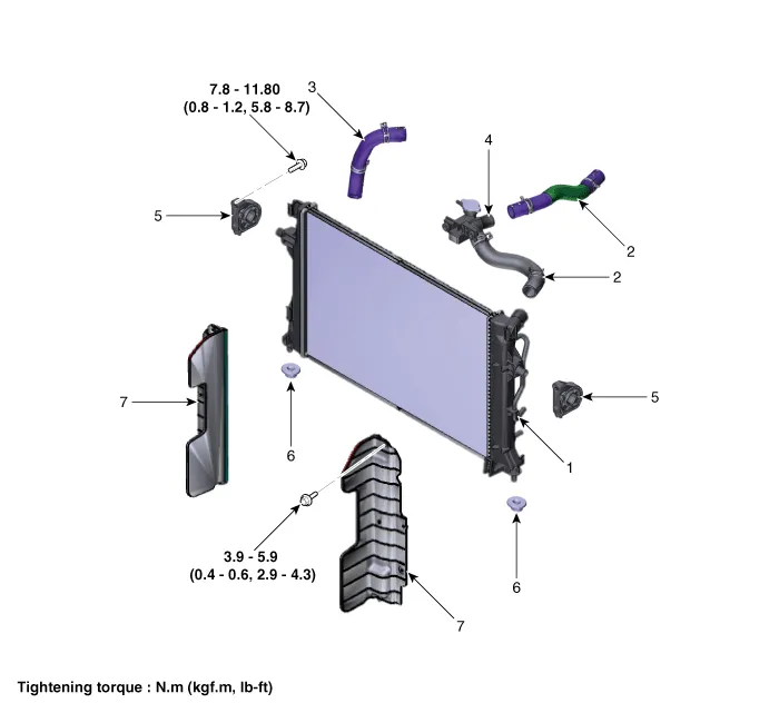
1 . Radiator
2 . Radiator upper hose
3 . Radiator lower hose
4 . Filler neck assembly
5. Radiator upper mounting bracket
6 . Radiator lower mounting insulator
7 . Radiator air guard
1.Disconnect the battery negative terminal.
2.Remove the cooling fan assembly. (Refer to Cooling System - "Cooling Fan")
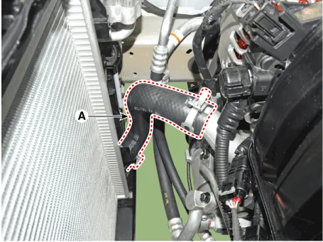
3.Disconnect the radiator lower hose (A).
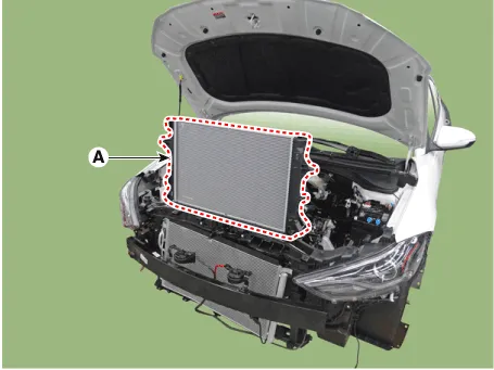
4.Separate the A/C condenser from the radiator and Remove the radiator (A) from the vehicle.
5.Install in the reverse order of removal.
6.Fill with engine coolant. (Refer to Cooling System - "Coolant")

• The coolant must be injected according to the integrated thermal management module (ITM) coolant filling method.
7.Start engine and check for leaks.
1.Remove the radiator cap, wet its seal with engine coolant, and then install it on a pressure tester.
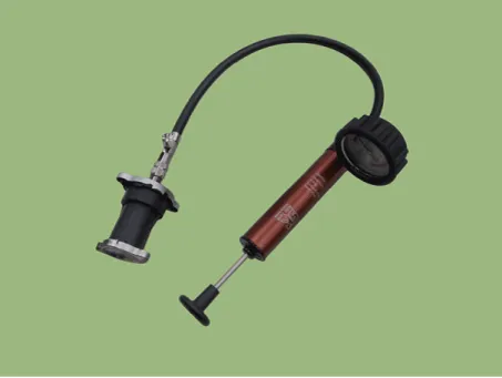
2.Apply a pressure of 93.16 - 122.58 kpa (0.95 - 1.25 kg/cm², 13.51 - 17.78 psi).
3.Check for a drop in pressure.
4.If the pressure drops, replace the cap.
1.Wait for the engine to cool. Carefully remove the radiator cap and fill the radiator with engine coolant. Then, install it on the pressure tester.
2.Apply a pressure tester to the radiator and apply a pressure of 93.16 - 122.58 kpa (0.95 - 1.25 kg/cm², 13.51 - 17.78 psi).
3.Inspect for engine coolant leaks and a drop in pressure.
4.Remove the tester and reinstall the radiator cap.

• Check for engine oil in the coolant and/or coolant in the engine oil.
Integrated Thermal Management Module (ITM) ➤
Water Inlet Fitting
1.Remove the engine room under cover.(Refer to Engine and Transaxle Assembly - "Engine Room Under Cover")
2.Drain the coolant. (Refer to Cooling System - "Coolant")
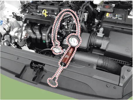
3.Disconnect the radiator lower hose (A).
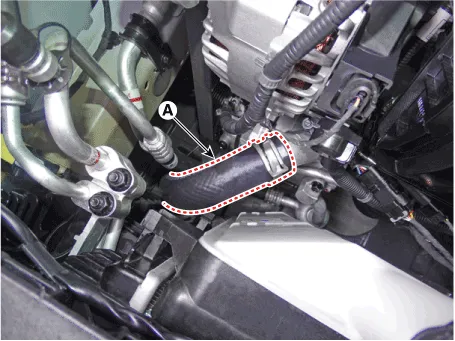
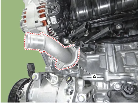
4.Remove the water inlet fitting (A).
Tightening torque : 18.6 - 23.5 N.m (1.9 - 2.4 kgf.m, 13.7 - 17.4 lb-ft)
5.Install in the reverse order of removal.

• Always use a new integrated thermal management module (ITM) O-ring.
• When assembling the hose, Use a product with EPDM rubber stability.
• If a hose lubricant is applied, fill the coolant after 30 minutes of assembly.
• Place the hose at the specified location of the stopper and assemble them together. The front side of stoppers should be in close contact with the hose. And then, place the clamp at the correct location.
6.Fill with engine coolant. (Refer to Cooling System - "Coolant")

• The coolant must be injected according to the integrated thermal management module (ITM) coolant filling method.
7.Start engine and check for leaks.
Water pump
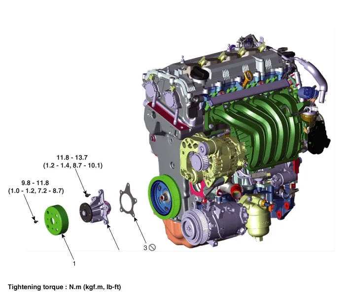
1. Water pump pulley
2. Water pump
3. Water pump gasket
1.Remove the engine room under cover.(Refer to Engine and Transaxle Assembly - "Engine Room Under Cover")
2.Drain the coolant. (Refer to Cooling System - "Coolant")
3.Remove the drive belt. (Refer to Timing System - "Drive Belt")
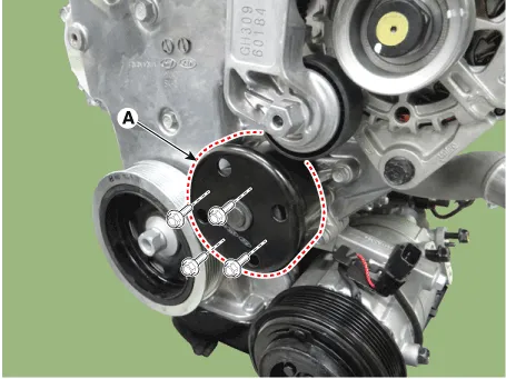
4.Remove the water pump pulley (A).
Tightening torque :9.8 - 11.8 N.m (1.0 - 1.2 kgf.m, 7.2 - 8.7 lb-ft)
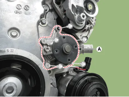
5.Remove the water pump (A) and gasket.
Tightening torque :11.8 - 13.7 N.m (1.2 - 1.4 kgf.m, 8.7 - 10.1 lb-ft)
6.Install in the reverse order of removal.

• Always use new water pump gasket.
• Check the specifications of the water pump instaling bolts. (Make sure that a solid sealant is applied to the thread of the bolt.)
• Always use new water pump bolts.
• Remove the sealant residue inside the bolt tap hole.
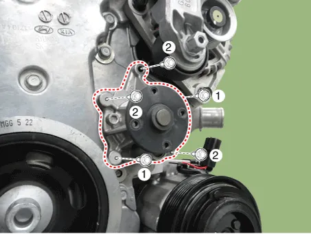
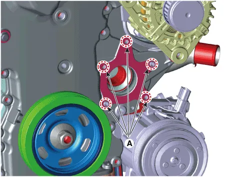
• When installing the water pump, tighten the bolts in the order shown in the figure below.
• Before installing the water pump, remove the hardened sealant, foreign matters, oil, dust, water, etc. off the inside hole (A) where the bolt is installed.
7.Fill with engine coolant. (Refer to Cooling System - "Coolant")

• The coolant must be injected according to the integrated thermal management module (ITM) coolant filling method.
8.Start engine and check for leaks.
| Trouble Symptom | Probable Cause | Remedy | ||||||||
| Coolant leakage |
| Visually check |
|
| ||||||
| ||||||||||
| ||||||||||

• From gaskets or bolts
• Check the tightening of the water pump mounting bolts.
• Retighten the mounting bolts.
• Check damage of gaskets or inflow of dust.
• Replace the gasket and clean dust off.
• From outer surface of water pump
• Check the material or any cracks of the water pump.
• Poor material. If any crack found, replace the water pump.
Noise
• From bearings
• From mechanical seals
• Impeller interference
Inspection with a stethoscope• After starting the engine, check noise with a stethoscope.
• If there is no noise, reuse the water pump (do not replace it).
• If there is any noise from the water pump, remove the drive belt and recheck.
Inspection after removing a drive belt
• After removing a water pump and a drive belt, check noise again
• If there is noise, reuse the water pump. (Check other drive line parts)
• If there is no noise, replace the water pump with a new one.
Inspection after removing a water pump
• Check water pump body and impeller interference.
• If there is any interference between them, replace the water pump with a new one.
Overheating
• Damaged impeller
• Loosened impeller
Loosened impeller• Corroded impeller insert
• Replace the water pump if it is separated by corrosion between impellers and inserts
• Replace the water pump if there is a crack in the PL impeller.
• Check engine coolant.
• Poor coolant quality / Maintenance check
• Impeller seperated from the shaft
• Replace the water pump.


Other information:
Hyundai Accent (HC) (2017 - 2022) Service Manual: Starter
- Specification Starter ItemSpecification Rated voltage12V, 0.9 kW The number of pinion teeth10 Performance[No-load, 11.5V]Ampere83.6 A Speed3,500 rpm - Components 1. Screw2. Front bracket3. Reducer assembly4. Lever5. Lever rest6. Magnet switch 7. Satellite gear8. Gasket sheet9. Armature assembly10. Yoke assembly11. Adjust washer12.Hyundai Accent (HC) (2017 - 2022) Service Manual: Warning and Indicator Lights
Information Make sure that all warning lights are OFF after starting the engine. If any light remains ON, it indicates a condition that requires attention. Air Bag Warning Light This warning light illuminates: When the ignition switch is turned to the ON position. - It illuminates for approximately 6 seconds and then turns off. When there is a malfunction in the Supplemental Restraint System (SRS).
Contents
- Troubleshooting
- Coolant
- Cooling Fan
- Radiator
- Integrated Thermal Management Module (ITM)
- Water Inlet Fitting
- Water pump
Categories
- Manuals Home
- Hyundai Accent Owners Manual
- Hyundai Accent Service Manual
- Questions & Answers
- Video Guides
- Useful Resources
- New on site
- Most important about car
- Privacy Policy

0.0053