Hyundai Accent (HC): Body Electrical System / Power Door Locks
Contents:
Components and Components Location
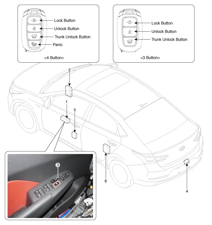
1. Driver power window main switch
2. Body Control Module (BCM)
3. Door look switch
4. Tailgate lock actuator
5. Front door lock actuator
6. Rear door lock actuator
Power Door Lock Actuators
1.Remove the front door trim.(Refer to Body - "Front Door Trim")
2.Remove the front door module.(Refer to Body - "Front Door Module")
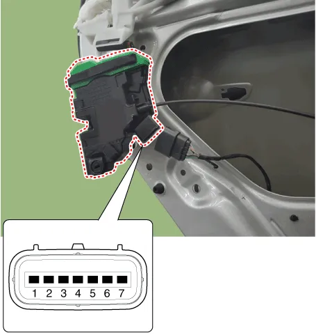
3.Disconnect the connectors from the actuator.
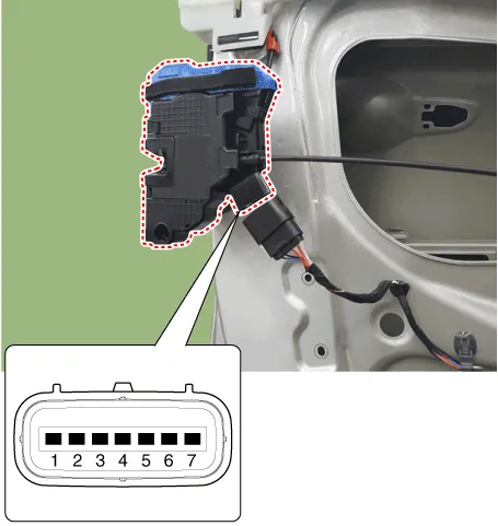
| No | Pin Information | |
| LH | RH | |
| 1 | Motor 1 | Lock / UnLock switch |
| 2 | Motor 2 | COM |
| 3 | - | Key Lock switch |
| 4 | Key Unlock switch | Key Unlock switch |
| 5 | Key Lock switch | - |
| 6 | COM | Motor 2 |
| 7 | Lock / UnLock switch | Motor 1 |
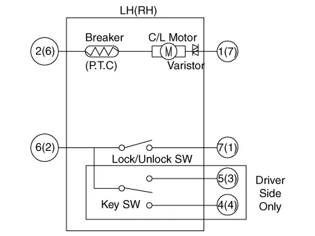
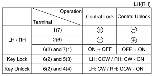
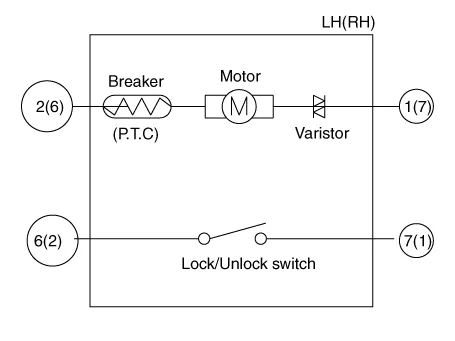
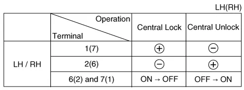
4.Check actuator operation by connecting power and ground according to the table. To prevent damage to the actuator, apply battery voltage only momentarily.
1.Remove the rear door trim.(Refer to Body - "Rear Door Trim")
2.Remove the rear latch.(Refer to Body - "Rear Door Latch")
3.Disconnect the connectors from the actuator.
| No | Pin Information | |
| LH | RH | |
| 1 | Motor 1 | Lock / UnLock switch |
| 2 | Motor 2 | COM |
| 3 | - | - |
| 4 | - | - |
| 5 | - | - |
| 6 | COM | Motor 2 |
| 7 | Lock / UnLock switch | Motor 1 |
4.Check actuator operation by connecting power and ground according to the table. To prevent damage to the actuator, apply battery voltage only momentarily.
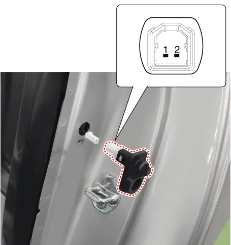
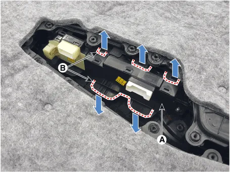
1.Remove the door switch (A) after loosening the screw and disconnecting the connector (B).
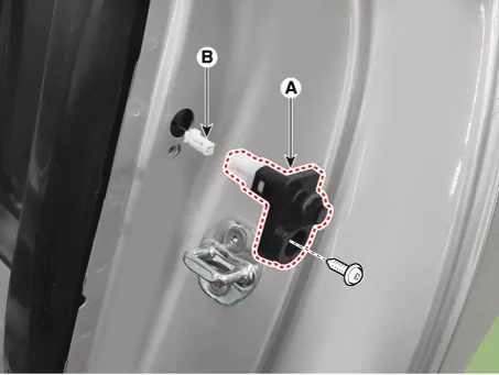
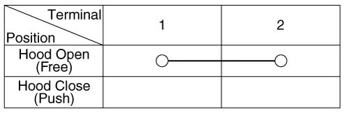
2.Check for continuity between the terminals in each switch position according to the table.
1.Remove the tailgate trim. (Refer to Body - "Tailgate Trim")
2.Disconnect the connector from the actuator.
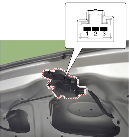
3.Check for continuity between the terminals in each switch position according to the table.

4.Check actuator operation by connecting power and ground according to the table. To prevent damage to the actuator, apply battery voltage only momentarily.

Power Door Lock Switch
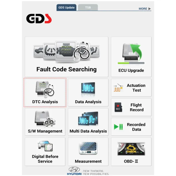
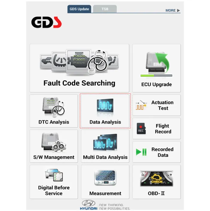
1.In the body electrical system, failure can be quickly diagnosed by using the vehicle diagnostic system (Diagnostic tool).The diagnostic system (Diagnostic tool) provides the following information.
(1)Fault Code Searching : Checking failure and code number (DTC)
(2)Data Analysis : Checking the system input/output data state
(3)Actuation test : Checking the system operation condition
(4)S/W Management : Controlling other features including system option setting and zero point adjustment
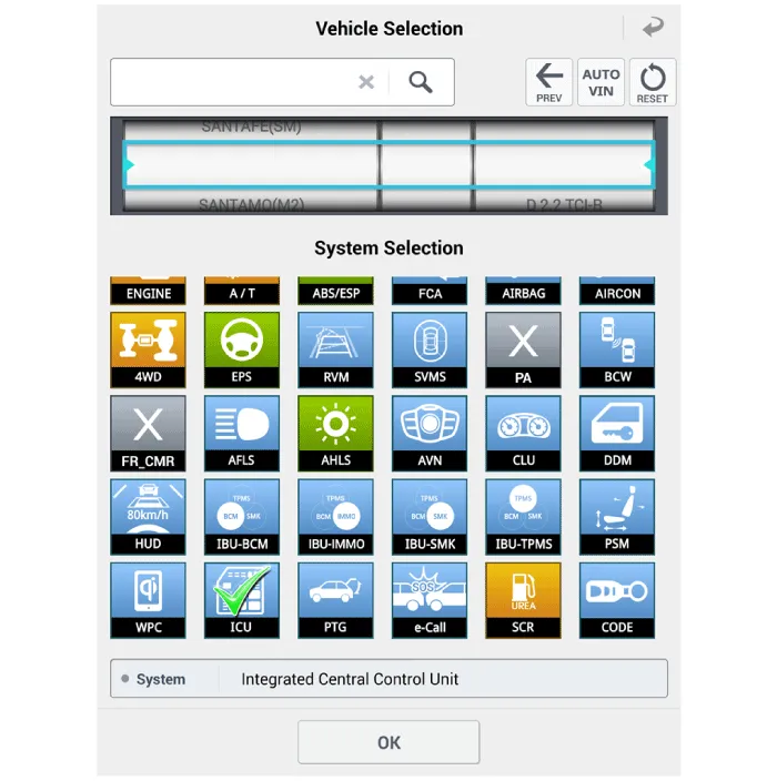
2.If diagnose the vehicle by Diagnostic tool, select "DTC Analysis" and "Vehicle".
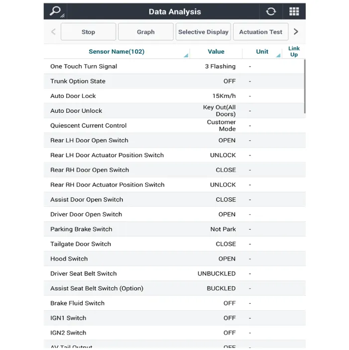
3.If check current status, select the "Data Analysis" and "Car model".
4.Select the 'ICU' to search the current state of the input/output data.
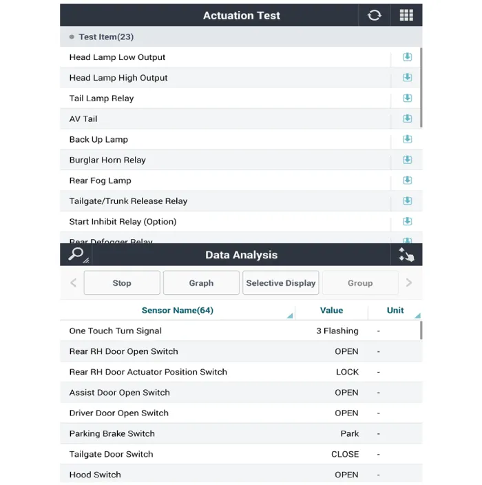
5.To forcibly actuate the input value of the module to be checked, select option 'Actuation Test'.
1.Disconnect the negative (-) battery terminal.
2.Remove the front door trim.(Refer to Body - "Front Door Trim")
3.Remove the power window switch assembly (A) by pulling out both ends of the switch holders (B).
1.Install the power window switch assembly.
2.Install the front door trim after connect the connector.


Other information:
Hyundai Accent (HC) (2017 - 2022) Service Manual: CVVT & Camshaft
- Description Continuous Variable Valve Timing (CVVT) system advances or retards the valve timing of the intake and exhaust valve in accordance with the ECM control signal which is calculated by the engine speed and load.By controlling CVVT, the valve over-lap or under-lap occurs, which makes better fuel economy and reduces exhaust gases (NOx, HC) and improves engine performance through reduction of pumping loss, internal EGR effect, improvement of combustion stability, improvement of volumetric efficiency, and increase of expansion work.Hyundai Accent (HC) (2017 - 2022) Service Manual: Scheduled maintenance services
Follow Normal Maintenance Schedule if the vehicle is usually operated where none of the following conditions apply. If any of the following conditions apply, you must follow the Maintenance Under Severe Usage Conditions. In other words, Hyundai Accent service intervals may need to be shorter when driving conditions are tougher than average. Repeated driving short distance of less than 5 miles (8 km) in normal temperature or less than 10miles (16 km) in freezing temperature Extensive engine id
Contents
Categories
- Manuals Home
- Hyundai Accent Owners Manual
- Hyundai Accent Service Manual
- Questions & Answers
- Video Guides
- Useful Resources
- New on site
- Most important about car
- Privacy Policy

0.0097