Hyundai Accent (HC): Brake System (ABS/ESC) / ESP(Electronic Stability Program) System
Contents:
- Description and Operation
- Components and Components Location
- Schematic Diagrams
- Repair procedures
- Troubleshooting
- ESP Control Unit
- ESP OFF Switch
- Front Wheel Speed Sensor
- Rear Wheel Speed Sensor
Description and Operation ➤
Components and Components Location
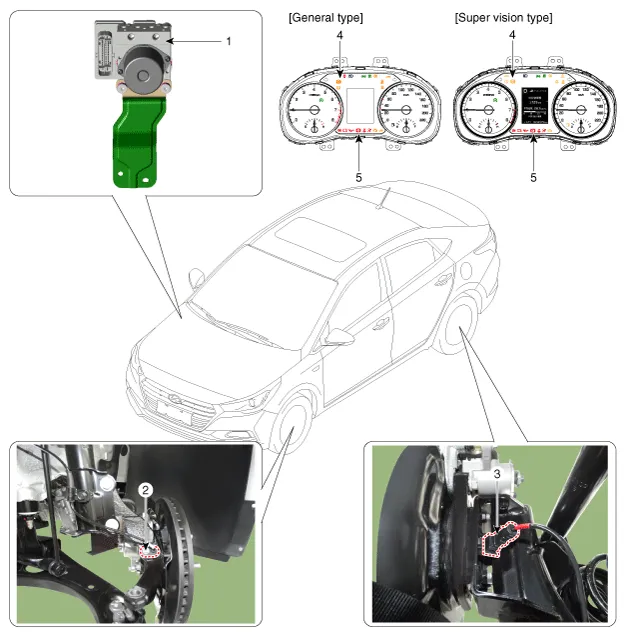
1. ESP Control Module (HECU)
2. Front Wheel Speed Sensor
3. Rear Wheel Speed Sensor
4. ESP Warning lamp
5. EBD / Parking brake warning lamp
Schematic Diagrams
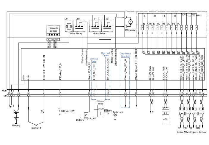
| Wire No | Designation | Current | |
| Max | Min | ||
| 13 | Ground for recirculation pump | 39A | 10A |
| 1 | Voltage supply for pump motor | 39A | 10A |
| 25 | Voltage supply for solenoid valves | 15A | 2A |
| 38 | Ground for solenoid valves andECU | 15A | 2A |
| 22 | Signal wheel speed sensor (FL) | 16.8 mA | 5.9 mA |
| 33 | Voltage supply for the active wheel speed sensor (RL) | 16.8 mA | 5.9 mA |
| 19 | Voltage supply for the active wheel speed sensor (RR) | 16.8 mA | 5.9 mA |
| 18 | Voltage supply for the active wheel speed sensor (FR) | 16.8 mA | 5.9 mA |
| 6 | Signal wheel speed sensor (FR) | 16.8 mA | 5.9 mA |
| 14 | C-CAN LOW | 30 mA | 20 mA |
| 34 | Voltage supply for the active wheel speed sensor (FL) | 16.8 mA | 5.9 mA |
| 20 | Signal wheel speed sensor (RL) | 16.8 mA | 5.9 mA |
| 32 | Voltage for HECU (IGN) | 1A | 500 mA |
| 31 | Signal wheel speed sensor (RR) | 16.8 mA | 5.9 mA |
| 30 | Brake light switch | 10 mA | 5 mA |
| 26 | C-CAN HIGH | 30 mA | 20 mA |
| 27 | Wheel speed sensor output | Open Draim | - |
| 8 | ESP switch | 10 mA | 5 mA |
| 23 | Clutch switch (MT Only) | 10 mA | 5 mA |
| 10 | Parking Brake switch | 10 mA | 5 mA |
| 21 | L-CAN LOW | 30 mA | 20 mA |
| 9 | L-CAN HIGH | 30 mA | 20 mA |
| 16 | HAC Drive signal | 200 mA | |
Repair procedures
1.Remove the reservoir cap and fill the brake reservoir with brake fluid.

ŌĆó If there is any brake fluid on any painted surface, wash it off immediately.
ŌĆó When pressure bleeding, do not depress the brake pedal.
ŌĆó Recommended fluid........ DOT3 or DOT4
2.Connect a clear plastic tube to the wheel cylinder bleeder plug and insert the other end of the tube into a half filled clear plastic bottle.
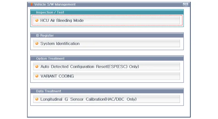
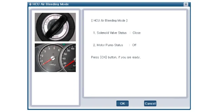
3.Connect the GDS to the data link connector located underneath the dash panel.
4.Select and operate according to the instructions on the GDS screen

ŌĆó You must obey the maximum operating time of the ESC motor with the GDS to prevent the motor pump from burning.
1)Select vehicle name.
2)Select ABS/ESC system.
3)Select HCU air bleeding mode.
5.Pump the brake pedal several times, and then loosen the bleeder
screw until fluid starts to run out without bubbles. Then close the
bleeder screw (A).
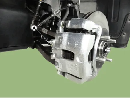
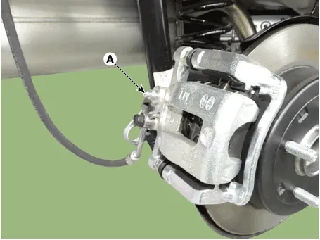
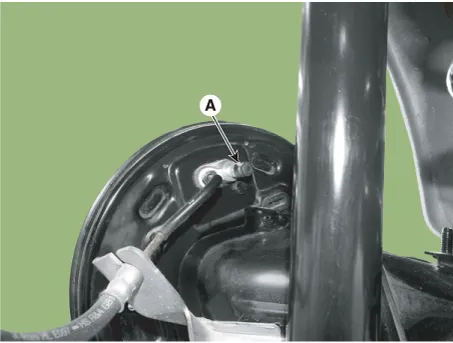
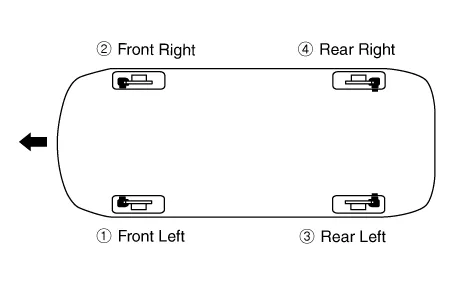
6.Repeat the procedure for wheel in the sequence shown below until air bubbles no longer appear in the fluid.
7.Refill the master cylinder reservoir to MAX (upper) level line.
Troubleshooting
1.In principle, ESP and TCS controls are prohibited in case of ABS failure.
2.When ESP or TCS fails, only the failed system control is prohibited.
3.However, when the solenoid valve relay should be turned off in case of ESP failure, refer to the ABS fail-safe.
4.Information on ABS fail-safe is identical to the fail-safe in systems where ESP is not installed.
1.It keeps the code as far as the backup lamp power is connected. (O)
2.It keeps the code as long as the HCU power is on. (X)
1.Initial checkup is performed immediately after the HECU power on.
2.Valve relay checkup is performed immediately after the IG2 ON.
3.It executes the checkup all the time while the IG2 power is on.
4.Initial checkup is made in the following cases.
(1)When no failure is detected
(2)When ABS and ESP are not in control.
(3)Initial checkup is not made after ECU power on.
(4)If the vehicle speed is over 5 mph(8 km/h) when the brake lamp switch is off.
(5)When the vehicle speed is over 24.8 mph(40 km/h).
5.Though, it keeps on checkup even if the brake lamp switch is on.
6.When performing ABS or ESP control before the initial checkup, stop the initial checkup and wait for the HECU power input again.
7.Judge failure in the following cases.
(1)When the power is normal.
(2)From the point in which the vehicle speed reaches 4.9 mph(8 km/h) after HECU power on.
1.Shut the system down and perform the following actions and wait for HECU power OFF.
2.Turn the valve relay off.
3.Do not perform any ABS/TCS/ESP functions until normal operating condition is restored.
1.ABS warning lamp turns on when ABS is malfunctioning.
2.ESP function/ warning lamp turns on when ESP is malfunctioning.When power voltage and valve relay voltage are abnormal, input/output related failure judgment is not made.
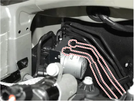
ESP Control Unit
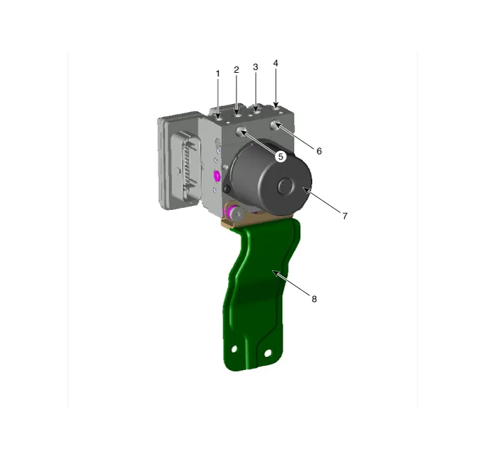
1. Front - right tube
2. Rear - left tube
3. Rear - right tube
4. Front - left tube
5. MC SEC
6. MC PRI
7. ESP control module (HECU)
8. Bracket
1.Turn the ignition switch OFF and then disconnect the negative (-) battery cable.
2.Pull up the lock of the HECU connector, then disconnect the connector.
3.Remove the brake fluid from the master cylinder reservoir with a syringe.

ŌĆó Be sure to completely remove foreign substances from around brake fluid reservoir and cap before opening the reservoir cap. If not, it may cause contamination of brake fluid and deterioration in braking performance.
ŌĆó Do not spill brake fluid on the vehicle, it may damage the paint; if brake fluid does contact the paint, wash it off immediately with water.
4.Disconnect the brake tubes from the HECU by unlocking the nuts counterclockwise with a spanner.
Tightening torque : 13.7 - 16.7 N.m (1.4 - 1.7 kgf.m, 10.1 - 12.3 lb-ft)
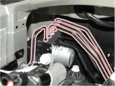
Tightening torque : 18.6 - 22.6 N.m (1.9 - 2.3 kgf.m, 13.7 - 16.6 lb-ft)
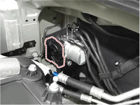
5.Loosen the HECU bracket bolts (A), then remove HECU and bracket.
Tightening torque :16.7 - 25.5 N.m (1.7 - 2.6 kgf.m, 12.3 - 18.8 lb-ft)
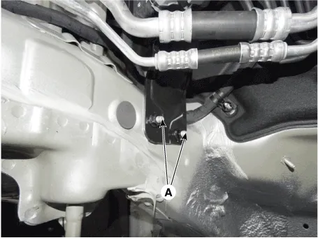
6.Remove the 3 bolts, then remove the bracket from HECU.
Tightening torque :7.8 - 9.8 N.m (0.8 - 1.0 kgf.m, 5.8 - 7.2 lb-ft)
1.To install, reverse the removal procedure.
2.Tighten the HECU mounting bolts and nuts to the specified torque.
3.After installation, bleed the brake system. (Refer to ESP(Electronic Stability Program) System - "ESP System Bleeding")
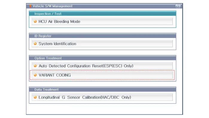
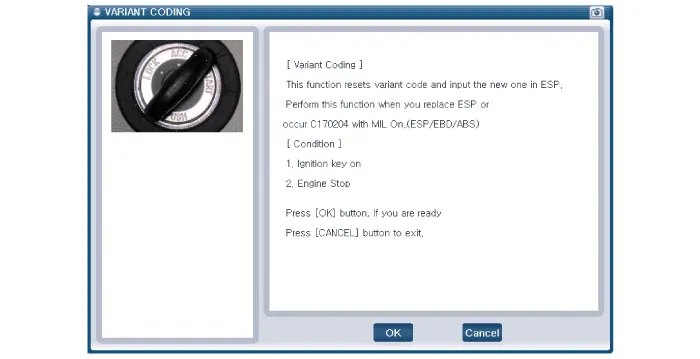
4.Conduct the Variant coding.
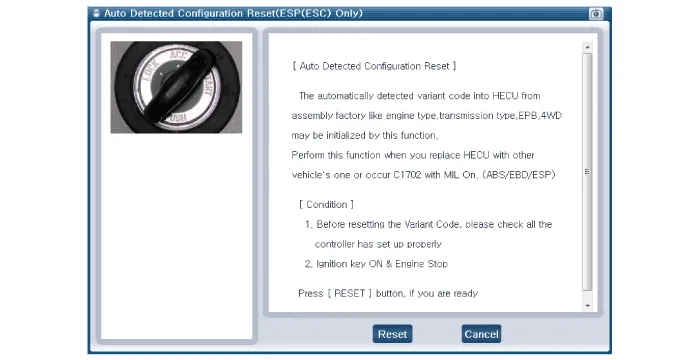
5.Conduct the Auto Detected Sensor Calibration.
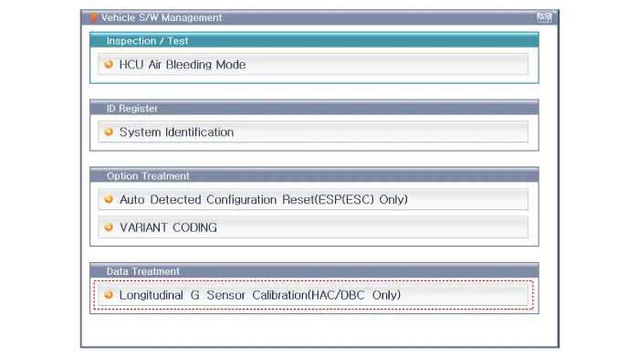
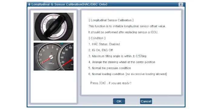
6.Conduct the Longitudinal G Sensor Calibration.
[Variant Coding]
[Auto Detected Sensor Calibration]
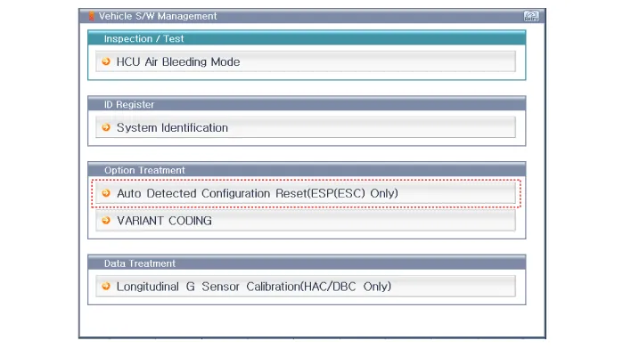
[Longitudinal G Sensor Calibration]
ESP OFF Switch
1.The ESP OFF switch is for the user to turn off the ESP system.
2.The ESP OFF lamp is on when ESP OFF switch is engaged.
1.Turn ignition switch OFF and disconnect the negative (-) battery cable.
2.Remove the crash pad lower panel.(Refer to Body - "Crash Pad")
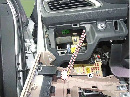
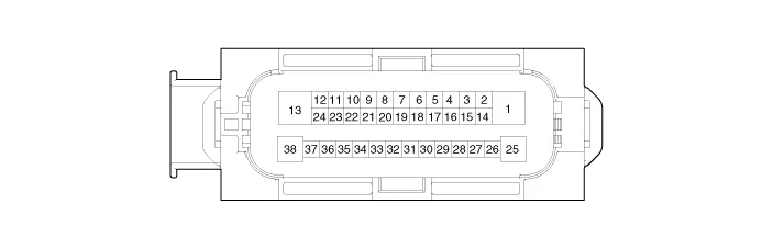
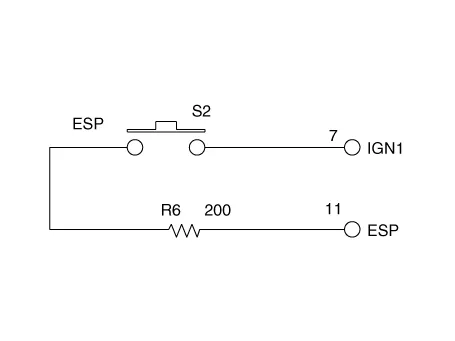
3.Check the continuity between the switch terminals as the ESP OFF switch is engaged.
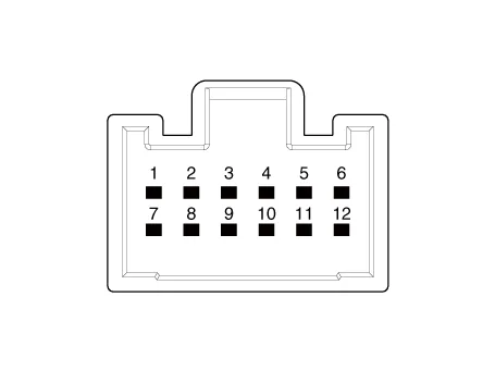
| No | Connector |
| 1 | IGS IGN (-) |
| 2 | - |
| 3 | GND |
| 4 | - |
| 5 | IGS |
| 6 | - |
| 7 | IGN1 |
| 8 | Tail |
| 9 | - |
| 10 | - |
| 11 | ESP |
| 12 | - |
Front Wheel Speed Sensor
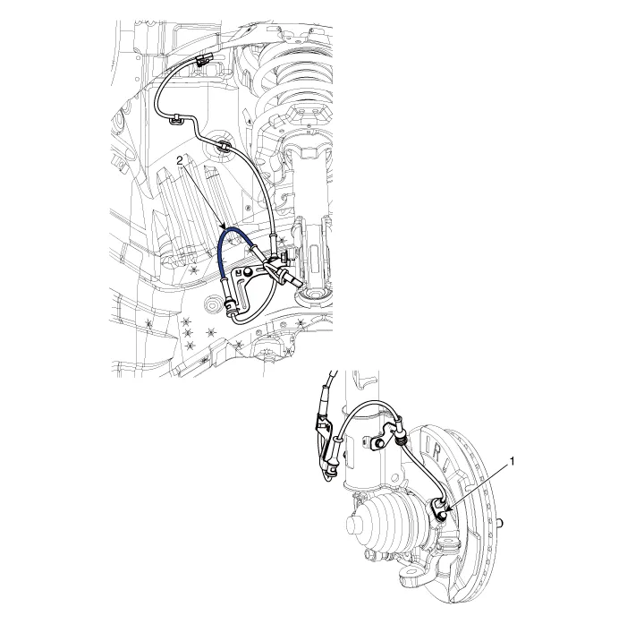
1. Front wheel speed sensor
2. Front wheel speed sensor cable
1.Loosen the wheel nuts slightly.Raise the vehicle, and make sure it is securely supported.
2.Remove the front wheel and tire (A) from the front hub.
Tightening torque :107.9 - 127.5 N.m (11.0 - 13.0 kgf.m, 79.6 - 94.0 lb-ft)
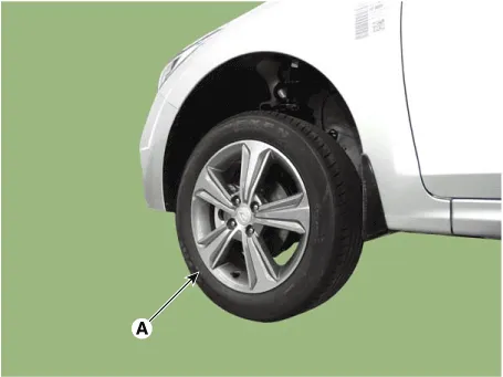

ŌĆó Be careful not to damage the hub bolts when removing the front wheel and tire.
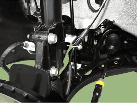
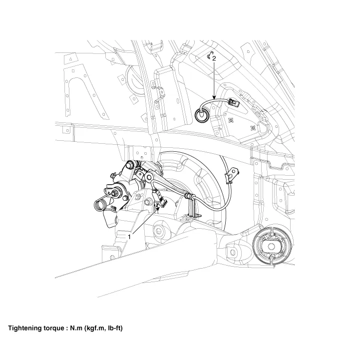
3.Loosen the mounting holt and then remove the wheel speed sensor cable from the strut assembly.
Tightening torque :7.8 - 11.8 N.m (0.8 - 1.2 kgf.m, 5.8 - 8.7 lb-ft)
4.Remove the wheel speed sensor cable braket bolt (A).
Tightening torque : 7.8 - 11.8 N.m (0.8 - 1.2 kgf.m, 5.8 - 8.7 lb-ft)

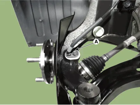
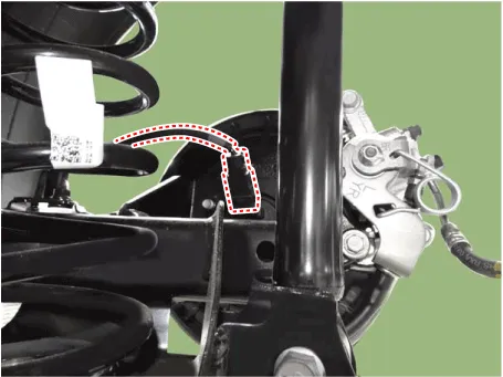
5.Loosen the bolt and then remove the wheel speed sensor (A).
Tightening torque :7.8 - 11.8 N.m (0.8 - 1.2 kgf.m, 5.8 - 8.7 lb-ft)
6.Remove the front wheel guard.(Refer to Body - "Front Wheel Guard")
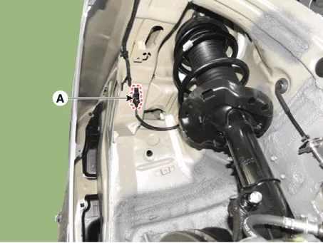
7.Disconnect the wheel speed sensor connector (A) and then remove it.
8.To install, reverse the removal procedure.
1.Measure the output voltage between the terminal of the wheel speed sensor and the body ground.

ŌĆó In order to protect the wheel speed sensor, when measuring output voltage, a 100╬® resister must be used as shown.
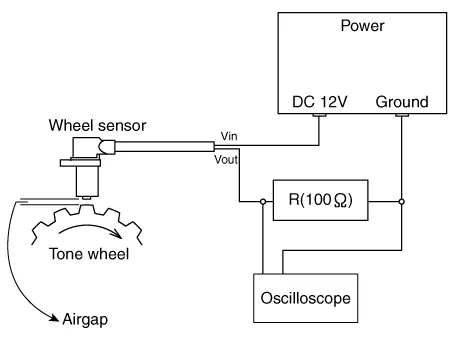
2.Compare the change of the output voltage of the wheel speed sensor to the normal change of the output voltage as shown below.
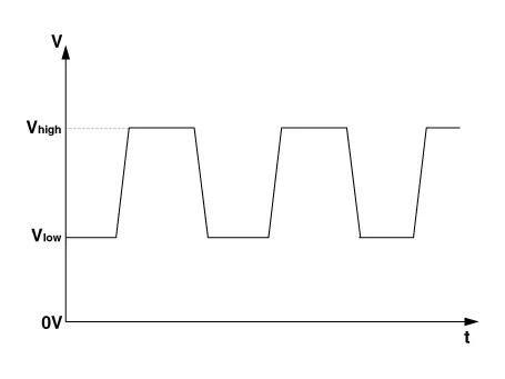
V_low : 0.59V - 0.84VV_high : 1.18V - 1.68VFrequency range : 1 - 2,500 Hz
Rear Wheel Speed Sensor
[Drum Type]

1. Front wheel speed sensor
2. Front wheel speed sensor cable
[Disc Type]
1. Front wheel speed sensor
2. Front wheel speed sensor cable
1.Loosen the wheel nuts slightly.Raise the vehicle, and make sure it is securely supported.
2.Remove the rear wheel and tire (A) from front hub.
Tightening torque :107.9 - 127.5 N.m (11.0 - 13.0 kgf.m, 79.6 - 94.0 lb-ft)


ŌĆó Be careful not to damage the hub bolts when removing the rear wheel and tire.
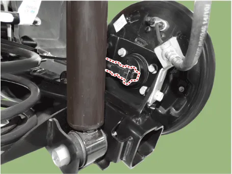
3.Disconnect the rear wheel speed sensor connector.
4.Loosen the screws and then remove the brake disc.
Tightening torque :4.9 - 5.9 N.m (0.5 - 0.6 kgf.m, 3.6 - 4.3 lb-ft)

5.Loosen the bolts and then remove the hub bearing.
Tightening torque :49.0 - 58.8 N.m (5.0 - 6.0 kgf.m, 36.2 - 43.4 lb-ft)


6.To install, reverse the removal procedure.
1.Loosen the wheel nuts slightly.Raise the vehicle, and make sure it is securely supported.
2.Remove the rear wheel and tire (A) from front hub.
Tightening torque :107.9 - 127.5 N.m (11.0 - 13.0 kgf.m, 79.6 - 94.0 lb-ft)
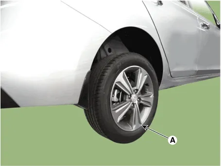

ŌĆó Be careful not to damage the hub bolts when removing the rear wheel and tire.
3.Loosen the screw and then remove the drum.
Tightening torque :4.9 - 5.9 N.m (0.5 - 0.6 kgf.m, 3.6 - 4.3 lb-ft)
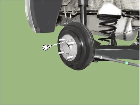
4.Disconnect the rear wheel speed sensor connector.
5.Loosen the hub mounting bolts (A) and then remove the hub from the torsion beam.
Tightening torque :44.1 - 53.9 N.m (4.5 - 5.5 kgf.m, 32.9 - 39.8 lb-ft)

6.To install, reverse the removal procedure.
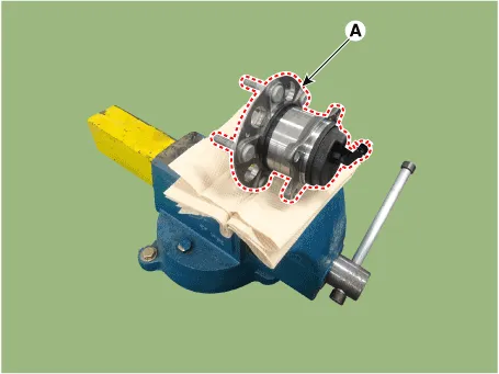
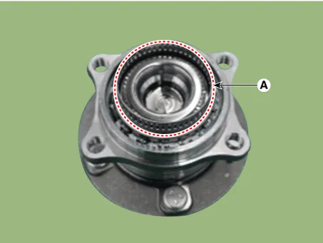
1.Remove the rear wheel hub bearing assembly.(Refer to Driveshaft and Axle - "Rear Hub - Carrier")
2.Fix the rear hub bearing assembly (A) on the vise.

ŌĆó When fixing on the vise, use a cloth not to be damaged the hub bearing assembly.
ŌĆó Be careful if excessive force for fixing on the vise may damage the hub bearing assembly.
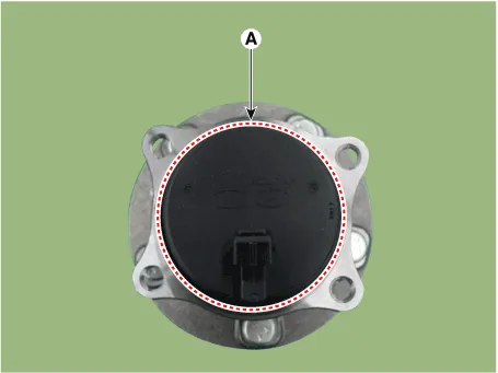
3.Check the direction of the sensor cap (A).
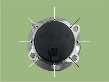
4.Remove the sensor cap by hammering on a gap between sensor cap and hub bearing assembly using a scraper (A).
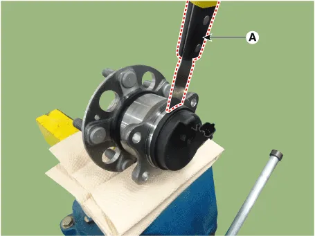

ŌĆó In order to widen the gap little by little, hammering around the bearing cap 10-20 times.
ŌĆó When removing the sensor cap, remove it in a straight direction not to damage the tone wheel or encoder.
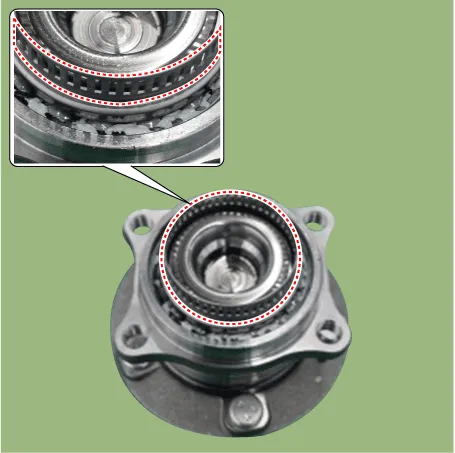
5.Check if distorted or damaged the tone wheel or encoder (A).

ŌĆó Check if damaged the tone wheel or encoder after removing the sensor cap and replace the hub bearing if it was deformed.
ŌĆó If the tone wheel is deformed, it may trigger the MIL ON or other problems.
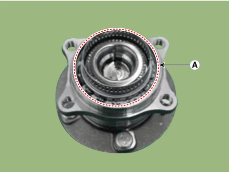
6.Position the sensor cap to the same direction of sensor cap connector (A) as you checked before removing.


ŌĆó Before installing the sensor cap, do not let any foreign material and contaminant into the hub bearing (A) assembly.
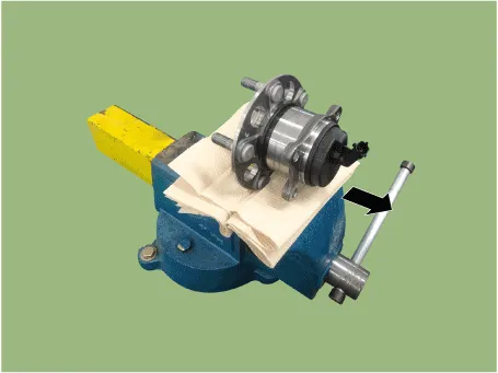
7.Install the sensor cap (A) with the special service tool (09527-1S010).
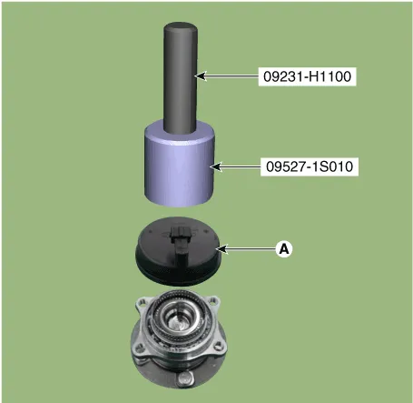

ŌĆó Hammer until there is no gap between the SST and hub bearing assembly and install the sensor cap.
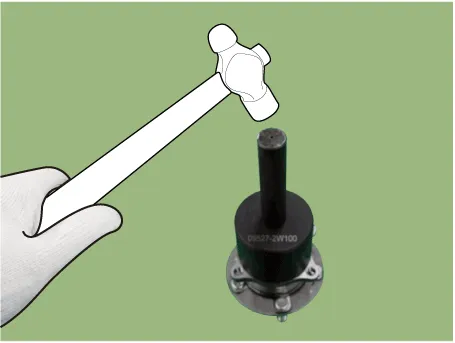
ŌĆó Be careful not to tilt to one side when installing the sensor cap as it may damage the tone wheel or encoder.
ŌĆó When sensor cap installation, hammering it until the gap disappeared between the sensor cap and hub bearing assembly.

8.Install the rear wheel hub bearing assembly.(Refer to Driveshaft and Axle - "Rear Hub - Carrier")
1.Measure the output voltage between the terminal of the wheel speed sensor and the body ground.

ŌĆó In order to protect the wheel speed sensor, when measuring output voltage, a 100╬® resister must be used as shown.

2.Compare the change of the output voltage of the wheel speed sensor to the normal change of the output voltage as shown below.

V_low : 0.59V - 0.84VV_high : 1.18V - 1.68VFrequency range : 1 - 2,500 Hz


Other information:
Hyundai Accent (HC) (2017 - 2022) Service Manual: Troubleshooting
- Basic Troubleshooting Basic Troubleshooting Guide Customer Problem Analysis Sheet Basic Inspection Procedure Measuring Condition Of Electronic Parts' Resistance The measured resistance at high temperature after vehicle running may be high or low. So all resistance must be measured at ambient temperature (20┬░C, 68┬░F), unless stated otherwise.Hyundai Accent (HC) (2017 - 2022) Service Manual: Tire Replacement
On the Hyundai Accent, a tire that wears evenly will eventually reveal the built-in tread wear indicators. These indicators appear as a solid, continuous band across the tread and confirm there is less than 2/32 inch (1.6 mm) of usable tread remaining. Replace the tire when this happens to help maintain safe braking performance, stable steering control, and reliable wet-weather traction.
Contents
- Description and Operation
- Components and Components Location
- Schematic Diagrams
- Repair procedures
- Troubleshooting
- ESP Control Unit
- ESP OFF Switch
- Front Wheel Speed Sensor
- Rear Wheel Speed Sensor
Categories
- Manuals Home
- Hyundai Accent Owners Manual
- Hyundai Accent Service Manual
- Questions & Answers
- Video Guides
- Useful Resources
- New on site
- Most important about car
- Privacy Policy

0.0086