Hyundai Accent (HC): Restraint
Contents:
- General Information
- Specifications
- Special Service Tools
- General Safety Information and Caution
- Description and Operation
- Repair procedures
- SRSCM
- Airbag Module
- Seat Belt Pretensioner
General Information
1.DC/ DC converter : DC/DC converter in power supply unit includes up/down transformer converter, and provides ignition voltage for all firing circuits, implemented as ASICs and the internal operation voltage of the SRSCM itself. if the internal operation voltage is below critical value setting, it will perform resetting.
2.Back up power supply : SRSCM has separate back up power supply, that will supply deployment energy instantly in low voltage condition or upon power failure by front crash.
3.Self diagnosis : SRSCM will constantly monitor current SRS operation status and detect system failure while vehicle power supply is on, system failure may be checked with trouble codes using GDS.
4.Airbag warning lamp on : Upon detecting error, the module will transmit signal to SRSCM indicator lamp located at cluster. MIL lamp will indicat to the driver that there is an SRS error. Upon ignition key on, SRS lamp will turn on for about six seconds.
5.Trouble code registration : Upon error occurrence in system, SRSCM will store DTC corresponding to the error. DTC can be cleared only by GDS. However, if an internal fault code is active or if a crash is recorded the fault clearing cannot be performed.
6.Self diagnostic connector : Data stored in SRSCM memory will be output to GDS or other external output devices through a connector located below driver side crash pad.
7.Once airbag is deployed, SRSCM should not be used again but replaced.
8.SRSCM will determine whether passenger fasten the seat belt by the signal from built-in switch in seat belt buckle, and deploy front seat airbag at each set crash speed.
9.Side airbag deployment will be determined by SRSCM that will detect satellite sensor impact signal upon side crash, irrespective to seat belt condition.
Specifications
| Item | Resistance (Ω) |
| Driver Airbag (DAB) | 2.2 - 6.0 |
| Passenger Airbag (PAB) | 1.6 - 6.0 |
| Side Airbag (SAB) | 1.6 - 6.0 |
| Curtain Airbag | 1.6 - 6.0 |
| Seat Belt Pretensioner (BPT) | 1.6 - 6.0 |
| Item | N.m | kgf.m | lb-ft |
| Supplemental Restraint System Control Module | 8 - 10 | 0.8 - 1.0 | 5.8 - 7.2 |
| Passenger Air Bag | 3.9 - 5.9 | 0.4 - 0.6 | 2.9 - 4.4 |
| Side Air Bag | 5.9 - 7.8 | 0.6 - 0.8 | 4.3 - 5.8 |
| Curtain Airbag | 7.8 - 11.8 | 0.8 - 1.2 | 5.8 - 8.7 |
| Seat Belt Retractor Pretensioner | 39.2 - 53.9 | 4.0 - 5.5 | 28.9 - 39.8 |
| Front Impact Sensor | 8 - 10 | 0.8 - 1.0 | 5.8 - 7.2 |
| Side Impact Sensor | 8 - 10 | 0.8 - 1.0 | 5.8 - 7.2 |
Special Service Tools
| Tool (Number and Name) | Illustration | Use |
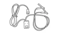
| Deployment tool 0957A-34100A |
| Airbag deployment tool. Use with (0957A-AL140) |
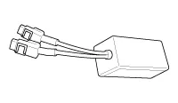
| Dummy 0957A-38200 |
| Simulator to check the resistanceof each wiring harness. Use with (0957A-AL170) |
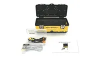
| Airbag deployment & dummy adapter kit 0957A-AL100 |
| Use with airbag deployment and airbag inspection |
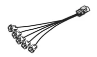
| Deployment adapter 0957A-AL140 |
| Use with deployment tool. (0957A-34100A) (DAB, PAB, BPT, CAB, APT) |
| Deployment adapter 0957A-AL150 |
| Use with deployment tool. (0957A-34100A) (SAB) |
| Dummy adapter 0957A-AL170 |
| Use with dummy (0957A-38200) (DAB, PAB, BPT, CAB, APT) |
| Dummy adapter 0957A-AL180 |
| Use with dummy (0957A-38200) (SAB) |
DAB : Driver AirbagPAB : Passenger AirbagBPT : Seat Belt PretensionerSAB : Side AirbagCAB : Curtain Airbag
General Safety Information and Caution
• Except when performing electrical inspections, always turn the ignition switch OFF and disconnect the negative cable from the battery, and wait at least three minutes before beginning work.

• Use the replacement parts which are manufactured to the same standards as the original parts and quality.Do not install used SRS parts from another vehicle. Use only new parts when making SRS repairs.
• Carefully inspect any SRS part before you install it. Do not install any part that shows signs of being dropped or improperly handled, such as dents, cracks or deformation.
• Before removing any of the SRSCM parts (including the disconnection of the connectors), always disconnect the SRSCM connector.
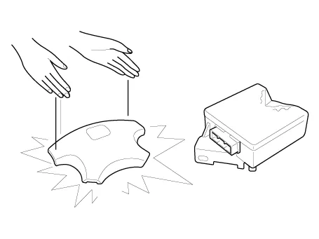
• Store the removed airbag with the pad surface up.
• Keep free from any oil, grease, detergent, or water to prevent damage to the airbag assembly.
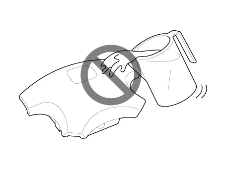
• Store the removed airbag on secure, flat surface away from any high heat source (exceeding 85 C/185 F).
• Never perform electrical inspections to the airbags, such as measuring resistance.
• Do not position yourself in front of the airbag assembly during removal, inspection, or replacement.
• Refer to the scrapping procedures for disposal of the damaged airbag.
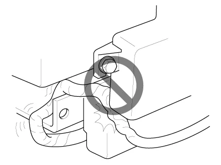
• Be careful not to bump or impact the SRS unit or the side impact sensors or front impact sensors whenever the ignition switch is ON, wait at least three minutes after the ignition switch is turned OFF before begin work.
• During installation or replacement, be careful not to bump (by impact wrench, hammer, etc.) the area around the SRS unit and the side impact sensor and the front impact sensors. The airbags could accidentally deploy and cause damage or injury.
• Replace the front airbag module, SRSCM, FIS when the front airbag is deployed. Replace the airbag wiring when the airbag wiring get damaged. Replace the side airbag module, the curtain airbag module, SRSCM, SIS when deploying the side airbag. Replace the airbag when the airbag wiring get damaged.
• After a collision in which the airbags or the side air bags did not deploy, inspect for any damage or any deformation on the SRS unit and the side impact sensors. If there is any damage, replace the SRS unit, the front impact sensor and/or the side impact sensors.
• Do not disassemble the SRS unit, the front impact sensor or the side impact sensors.
• Turn the ignition switch OFF, disconnect the battery negative cable and wait at least three minutes before beginning installation or replacement of the SRS unit.
• Be sure the SRS unit, the front impact sensor and side impact sensors are installed securely with the mounting bolts.
• Do not spill water or oil on the SRS unit, or the front impact sensor or the side impact sensors and keep them away from dust.
• Store the SRS unit, the front impact sensor and the side impact sensors in a cool (15 - 25°C/ 59 - 77°F) and dry (30 - 80% relative humidity, no moisture) area.
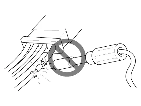
• Never attempt to modify, splice, or repair SRS wiring. If there is an open or damage in SRS wiring, replace the harness.
• Be sure to install the harness wires so that they are not pinched, or interfere with other parts.
• Make sure all SRS ground locations are clean, and grounds are securely fastened for optimum metal-to-metal contact. Poor grounding can cause intermittent problems that are difficult to diagnose.
• When using electrical test equipment, insert the probe of the tester into the wire side of the connector.Do not insert the probe of the tester into the terminal side of the connector, and do not tamper with the connector.
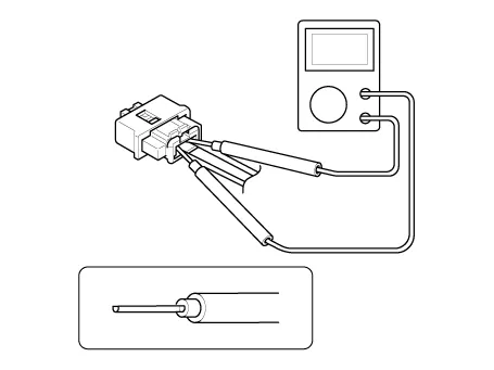
• Use a u-shaped probe. Do not insert the probe forcibly.
• Use specified service connectors for troubleshooting.Using improper tools could cause an error in inspection due to poor metal contact.
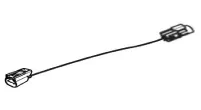
Disconnecting
To release the lock, pull the spring-loaded sleeve (A) and the slider (B), while holding the opposite half of the connector.Pull the connector halves apart. Be sure to pull on the sleeve and not on the connector half.

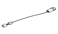
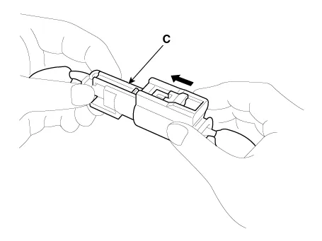
Connecting
Hold both connector halves and press firmly until the projection (C) of the sleeve-side connector clicks to lock.
Description and Operation
1.Active fault.
2.Normal or historical fault only exist.
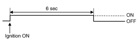
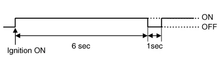
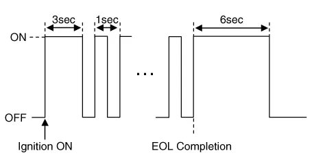
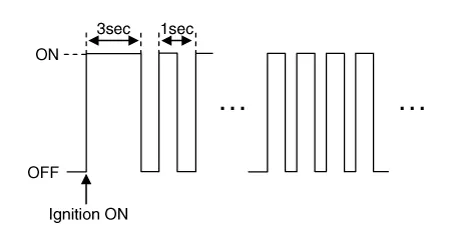
3.When turning the ignition switch ON during variant coding (EOL) mode, the airbag warning lamp is turned on and blinks at intervals of 1 second till the coding is completed.If the variant coding is completed normally, the airbag warning lamp will turn on for 6 seconds, and then turned off. Otherwise the airbag warning lamp continuously blinks at intervals of 1 second.
(1)In case the variant coding is normally completed
(2)In case the variant coding is not completed
1.Loss of battery supply to the SRSCM : warning lamp turned on continuously.
2.Loss of internal operating voltage : warning lamp turned on continuously.
3.Loss of Microprocessor operation : warning lamp turned on continuously.
4.SRSCM not connected : warning lamp turned on continuously.
Repair procedures

• Before doing any SRS repairs, use the GDS Pro to check for DTCs. Refer to the Diagnostic Trouble Code list for repairing of the related DTCs.
When the front airbag(s) deployed after a collision, replace the following items.– SRSCM
– Deployed airbag(s)
– Seat belt pretensioner(s)
– Front impact sensors
– SRS wiring harnesses
– Inspect the clock spring for heat damage.If any damage found, replace the clock spring.
When the side/curtain airbag(s) deployed after a collision, replace the following items.– SRSCM
– Deployed airbag(s)
– Side impact sensor(s) for the deployed side(s)
– SRS wiring harnesses
– Seat belt pretensioner(s)
After the vehicle is completely repaired, confirm the SRS airbag system is OK.– Turn the ignition switch ON; the SRS indicator should come on for about six seconds and then go off.
SRSCM ➤
Airbag Module ➤
Seat Belt Pretensioner ➤


Other information:
Hyundai Accent (HC) (2017 - 2022) Service Manual: Windshield defrosting and defogging
WARNING Windshield heating Do not use the or position during cooling operation in extremely humid weather. The difference between the temperature of the outside air and that of the windshield could cause the outer surface of the windshield to fog up, causing loss of visibility could cause an accident resulting in serious injury or death. In this case, set the mode selection knob or button to the position and fan speed control knob or button to a lower speed.Hyundai Accent (HC) (2017 - 2022) Service Manual: Stop Lamp Switch
- Components 1. Brake pedal member assembly2. Stop lamp switch3. Brake pedal arm 4. Pedal pad - Schematic Diagram - System circuit diagram - Terminal function TerminalDescription 1IGN 2BS 3- 4B+ 5BLS 6GND - Adjustment 1.Turn ignition switch OFF and disconnect the negative (-) battery cable. 2.Remove the lower crash pad.
Contents
- General Information
- Specifications
- Special Service Tools
- General Safety Information and Caution
- Description and Operation
- Repair procedures
- SRSCM
- Airbag Module
- Seat Belt Pretensioner
Categories
- Manuals Home
- Hyundai Accent Owners Manual
- Hyundai Accent Service Manual
- Questions & Answers
- Video Guides
- Useful Resources
- New on site
- Most important about car
- Privacy Policy

0.0072