Hyundai Accent (HC): Restraint / SRSCM
Contents:
- Components and Components Location
- Schematic Diagrams
- SRS Control Module (SRSCM)
- Front Impact Sensor (FIS)
- Side Impact Sensor (SIS)
- Occupant Classification System (OCS)
Components and Components Location
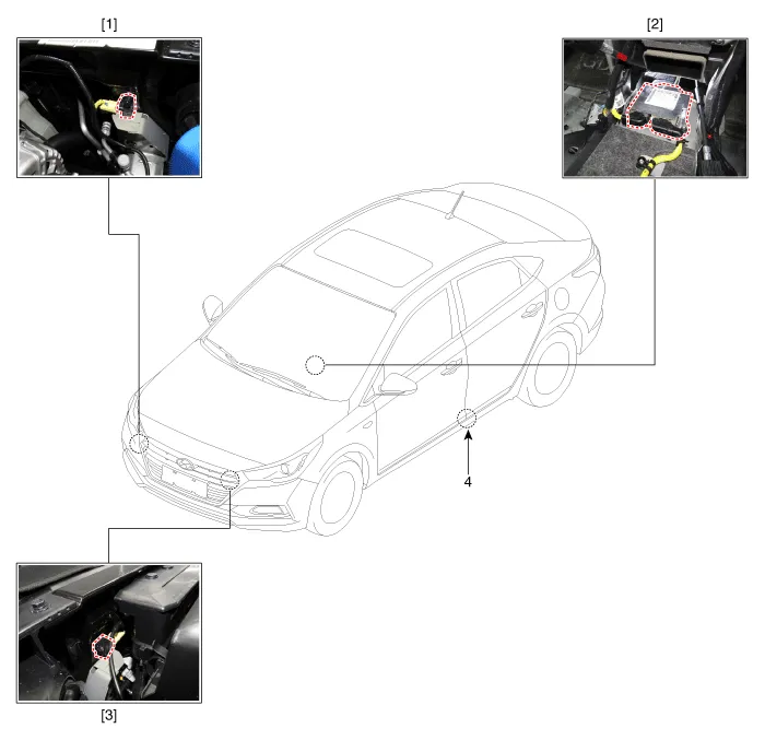
1. Front right Impact Sensor (FIS)
2. Supplemental Restraint System Control Module (SRSCM)
3. Front left Impact Sensor (FIS)
4. Gravity Side Impact Sensor (G-SIS)
Schematic Diagrams
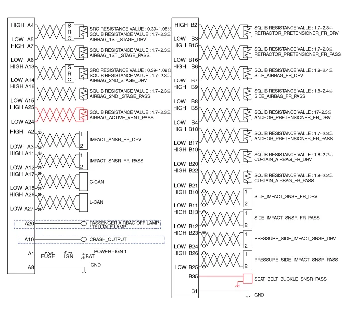
SRS Control Module (SRSCM)
• Supplemental Restraint System Control Module (SRSCM) determines whether and when to deploy air bag module, seat belt pretensioner (BPT).
• It supplies the air bag module with the power required to deploy the module or the BPT.
• It also performs self-diagnosis function of the supplemental restraint system.
1. Supplemental Restraint System Control Module (SRSCM)
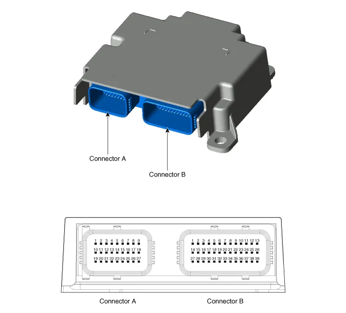
| No | Connector A | Connector B |
| 1 | IGN 1 | Ground |
| 2 | Front driver Impact sensor (+) | Front driver seat belt pretensioner (+) |
| 3 | Front driver Impact sensor (-) | Front driver seat belt pretensioner (-) |
| 4 | Driver airbag 1st stage (+) | Drive anchor pretensioner (-) |
| 5 | Driver airbag 1st stage (-) | Drive anchor pretensioner (+) |
| 6 | Passenger airbag 1st stage (-) | Front driver side airbag (+) |
| 7 | Passenger airbag 1st stage (+) | Front driver side airbag (-) |
| 8 | Ground | Front passenger side airbag (-) |
| 9 | - | Front passenger side airbag (+) |
| 10 | Crash output | Front driver side impact sensor (+) |
| 11 | Front passenger impact sensor (+) | Front driver side impact sensor (-) |
| 12 | Front passenger impact sensor (-) | Front passenger side impact sensor (-) |
| 13 | Drive airbag 2ND stage (+) | Front passenger side impact sensor (+) |
| 14 | Drive airbag 2ND stage (-) | - |
| 15 | Passenger airbag 2ND stage (+) | Front passenger seat belt pretensioner (+) |
| 16 | Passenger airbag 2ND stage (-) | Front passenger seat belt pretensioner (-) |
| 17 | C-CAN (High) | Passenger anchor pretensioner (-) |
| 18 | C-CAN (Low) | Passenger anchor pretensioner (+) |
| 19 | - | Front driver curtain airbag (+) |
| 20 | Passenger airbag OFF ind | Front driver curtain airbag (-) |
| 21 | - | Front passenger curtain airbag (-) |
| 22 | - | Front passenger curtain airbag (+) |
| 23 | - | Drive pressure side impact sensor (+) |
| 24 | Passenger active vent (-) | Drive pressure side impact sensor (-) |
| 25 | Passenger active vent (+) | Passenger pressure side impact sensor (+) |
| 26 | L-CAN (High) | Passenger pressure side impact sensor (-) |
| 27 | L-CAN (Low) | - |
| 28 | - | |
| 29 | - | |
| 30 | - | |
| 31 | - | |
| 32 | - | |
| 33 | - | |
| 34 | - | |
| 35 | Passenger seat belt buckle sensor (+) | |
| 36 | - | |
| 37 | - | |
| 38 | - | |
| 39 | - |
1.Remove the ignition key from the vehicle.
2.Disconnect the battery negative cable and wait for at least three minutes before beginning work.
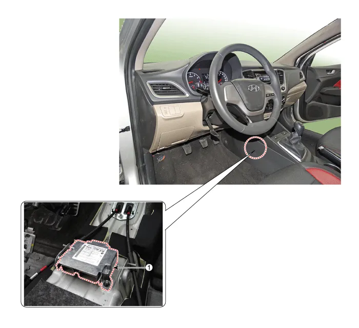
3.Remove the floor console.(Refer to Body - "Floor Console Assembly")
4.Disconnect the SRSCM connectors.
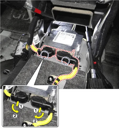
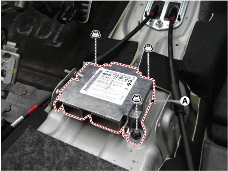
5.Remove the SRSCM (A) after loosening the mounting nuts.
1.Remove the ignition key from the vehicle.
2.Disconnect the battery negative cable and wait for at least three minutes before beginning work.
3.Install the SRSCM (A) with the SRSCM mounting nuts.
Tightening torque :7.8 - 9.8 N.m (0.8 - 1.0 kgf.m, 5.8 - 7.2 lb-ft)

4.Connect the SRSCM harness connectors.
5.Install the heater ducts and floor console.(Refer to Body - "Floor Console Assembly")
6.Reconnect the battery negative cable.
7.After installing the SRSCM, confirm proper system operation :Turn the ignition switch ON; the SRS indicator light should be turned on for about six seconds and then go off.

1)On SRSCM variant coding mode, the airbag warning lamp periodically blinks (ON : 0.5 sec., OFF : 0.5 sec.) until the coding is normally completed.
2)If the variant coding fails, DTC B176200 (ACU Coding Error) will be displayed and the warning lamp will turn on.In this case, perform the variant coding procedure again after confirming the cause in "DTC Fault State Information".Variant Coding can be performed up to 255 times, but if the number of coding work exceeds 255 times, DTC B168300 (Exceed Maximum coding Number) will be displayed and SRSCM must be replaced.
3) If the battery voltage is low (less than 9V), DTC B110200 will be displayed. In this case, charge the battery before anything else, and then perform the variant coding procedure. DTC B176200 (ACU Coding Error) and B110200 (Battery Voltage Low) may be displayed simultaneously.
â– On-line Type on GDS
1.Turn the ignition switch OFF.
2.Connect the GDS.
3.Turn the ignition switch ON without the engine running.
4.Select vehicle name and airbag system.
5.Select variant coding mode.
6.Follow the steps on the screen below.
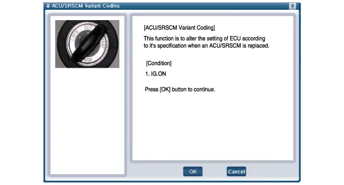
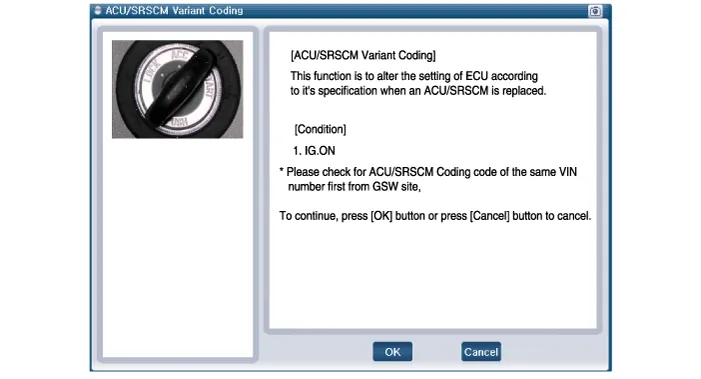
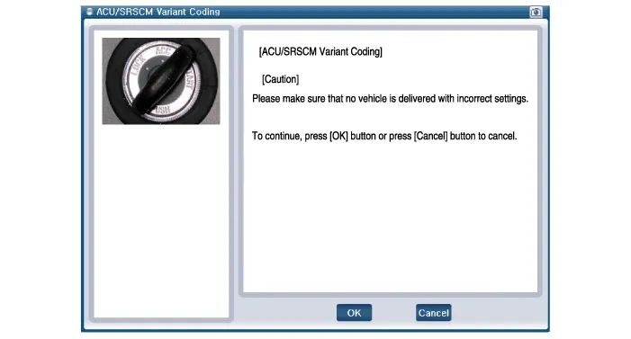
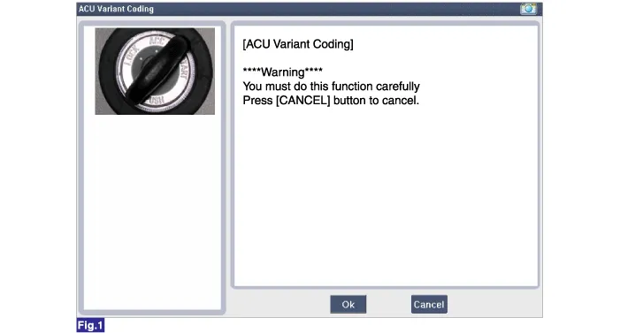
(1)Initial ACU Variant Coding screen
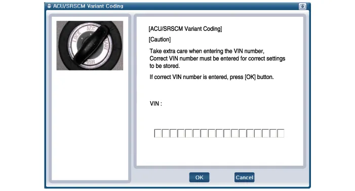
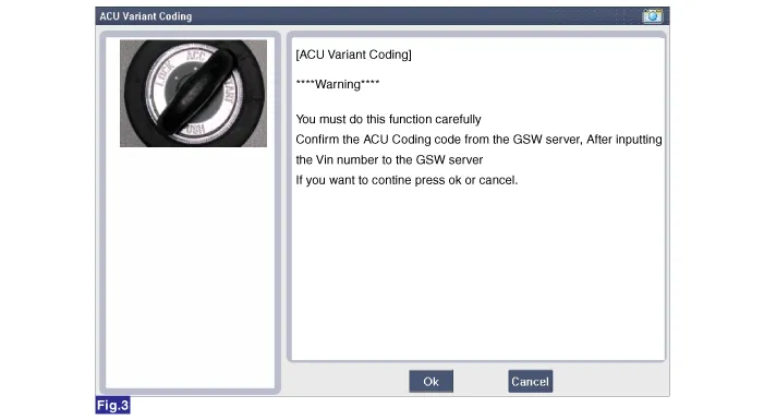
(2)VIN Code entering screen
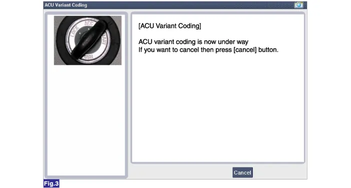
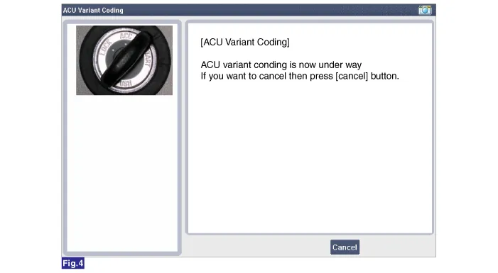
(3)Variant Coding's proceeding screen-1
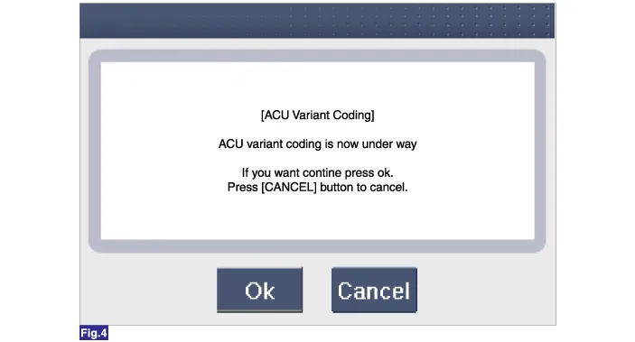
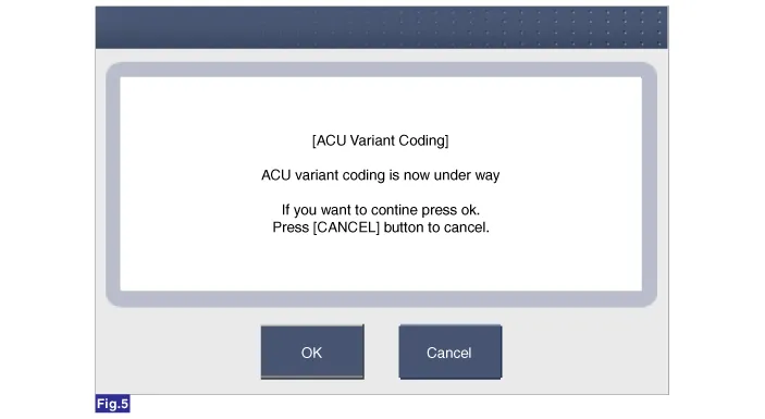
(4)Variant Coding's proceeding screen-2
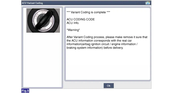
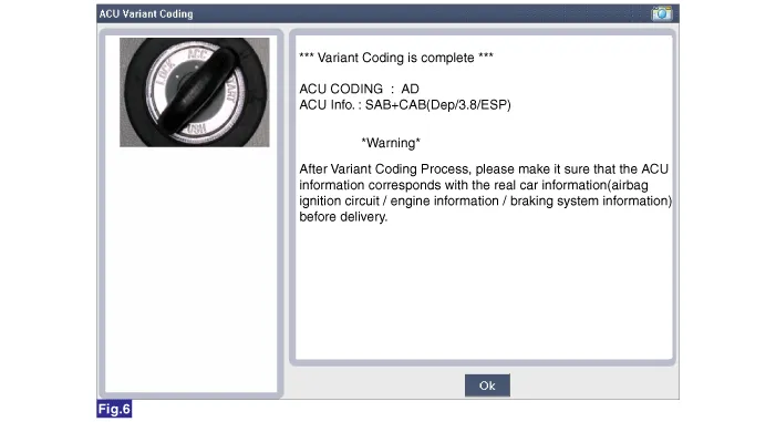
(5)Variant Coding is completed

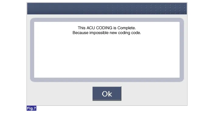
1)This screen is shown when you try variant coding on the SRSCM which has been performed before.
2)This screen is shown when communication failure has occurred.
1.Turn the ignition switch OFF.
2.Connect the GDS.
3.Turn the ignition switch ON without the engine running.
4.Select vehicle name and airbag system.
5.Select variant coding mode.
6.Follow the steps on the screen below.
(1)Initial ACU Variant Coding screen
(2)ACU Coding Code entering screen
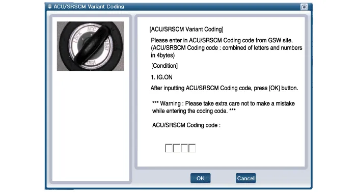
(3)Rechecking ACU Coding Code entering screen
(4)Variant Coding's proceeding screen-1
(5)Variant Coding's proceeding screen-2
(6)Variant Coding is completed

1)This screen is shown when you try variant coding on the SRSCM which has been performed before.
Front Impact Sensor (FIS)
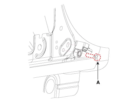
• The front impact sensors (FIS) are installed on the upper of the side panel in Front End Module (FEM). They are remote sensors that detect acceleration due to a collision at their mounting locations.
• The primary purpose of the Front Impact Sensor (FIS) is to provide an indication of a collition. The Front Impact Sensor (FIS) sends acceleration data to the SRSCM.
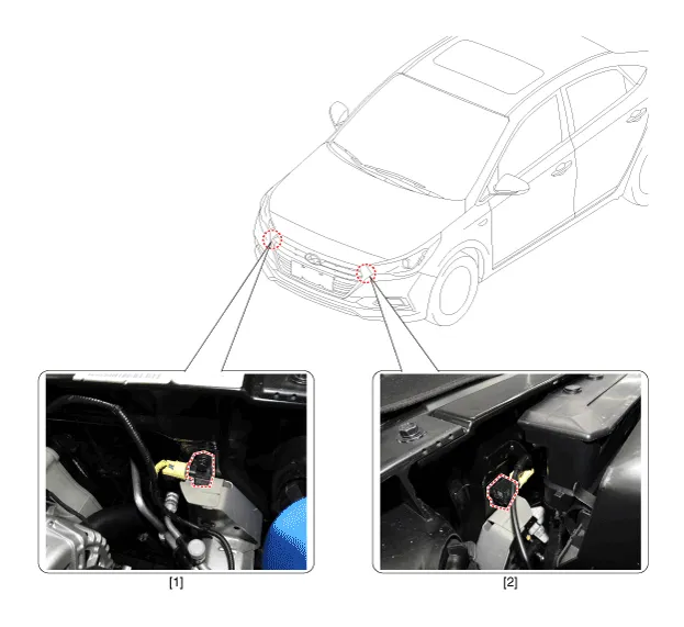
1. Front right Impact Sensor (FIS)
2. Front left Impact Sensor (FIS)

• Removal of the airbag must be performed according to the precautions/ procedures described previously.
• Before disconnecting the front impact sensor connector, disconnect the front airbag connector(s).
• Do not turn the ignition switch ON and do not connect the battery cable while replacing the front impact sensor.
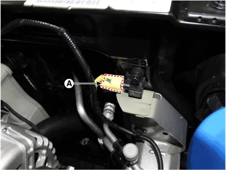
1.Disconnect the battery negative cable, and wait for at least three minutes before beginning work.
2.Disconnect the front impact sensor connector (A).
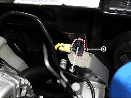
3.Remove the front impact sensor (A) after loosening the mounting bolt.

• Do not turn the ignition switch ON and do not contact the battery cable while replacing the front impact sensor.
1.Install the new front impact sensor.
2.Connect the front impact sensor connector.
3.Install the front impact sensor mounting bolt.
Tightening torque : 7.8 - 9.8 N.m (0.8 - 1.0 kgf.m, 5.8 - 7.2 lb-ft)
4.Reconnect the battery negative cable.
5.After installing the Front Impact Sensor, confirm proper system operation :
• Turn the ignition switch ON; the SRS indicator light should be turned on for about six seconds and then go off.
Side Impact Sensor (SIS)
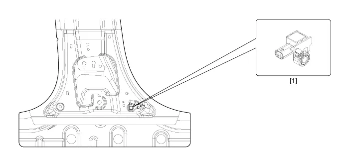
1. Side Impact Sensor (SIS)
1.Disconnect the battery negative cable and wait for at least three minutes before beginning work.
2.Remove the door scuff trim. (Refer to the Body group - "Interior trim")
3.Remove the center pillar trim. (Refer to the Body group - "Interior trim")
4.Loosen the side impact sensor mounting bolt (A) and remove the side impact sensor.


• Do not turn the ignition switch ON and do not connect the battery cable while replacing the side impact sensor.
1. Install the new side impact sensor with the bolt (A) then connect the side impact sensor connector.
Tightening torque : 7.0 - 9.0 N.m (0.71 - 0.92 kgf.m, 5.2 - 6.6 lb-ft)
2.Install the center pillar trim.(Refer to Body - "Interior tirm")
3.Install the door scuff trim. (Refer to Body - "Interior tirm")
4.Reconnect the battery negative cable.
5.After installing the Side Impact Sensor, confirm proper system operation :
• Turn the ignition switch ON; the SRS indicator light should be turned on for about six seconds and then go off.
Occupant Classification System (OCS)

1. OCS (Occupant Classification System) Unit
2. OCS (Occupant Classification System) Sensor
3. Passenger Seat
1.Disconnect the battery negative cable, and wait for at least three minutes before beginning work.
2.Remove the front passenger seat assembly.(Refer to Body - "Front Seat Assembly")
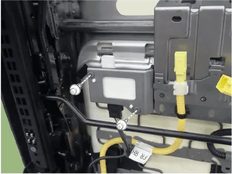
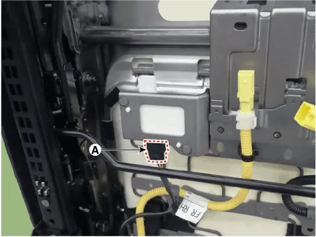
3.Disconnect the OCS ECU connector (A).

4.Remove the OCS mounting bolts.
1.Disconnect the battery negative cable, and wait for at least three minutes before beginning work.
2.Remove the front passenger seat assembly.(Refer to Body - "Front Seat Assembly")
3.Remove the front seat cushion cover.(Refer to Body - "Front Seat Cusion Cover")
4.Remove the front seat cushion assembly.(Refer to Body - "Front Seat Cushion Cover")
1.Install the occupant classification system unit on the Front seat track assembly.

2.Connect the occupant classification system unit connector.
3.Install the front passenger seat assembly.(Refer to Body - "Front Seat Assembly")
4.Reconnect the battery negative cable.
5.After installing the occupant classification system, confirm proper system operation.

• Turn the ignition switch ON the SRS indicator should be turned on for about six seconds and then go off.
• Telltale lamp will turn on for 4 seconds and be turned off for 3 seconds. After the 7 seconds, it shall remain off if the OCS does not require suppression and the passenger airbag is enabled.
• Be sure to perform OCS zeroing with GDS after replacing OCS equipped seat cushion.
1.Ignition "OFF", connect GDS.
2.Ignition "ON" & Engine "OFF", select Airbag system and "Body Sensor Reset" mode.
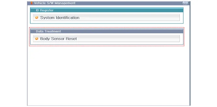
3.The GDS will show the two OCS Reset function steps.
(1)Erase OCS diagnostic codes.
(2)OCS initialization.
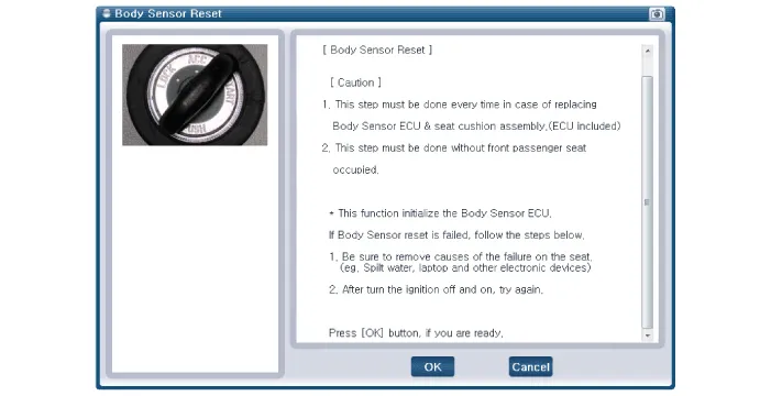

• This Step must be done during front passenger seat empty.
4.Select product configuration.
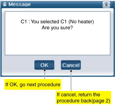
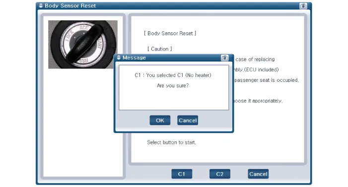
(1)C1 : No heater
(2)C2 : Heater
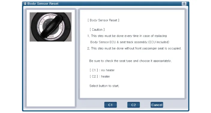

• Before the starting the OCS Rest process, cross check seat correct configuration with actual vehicle.
• If you see the center console, you can find different buttons per each different seat configuration type. (Refer to the below picture)
5.The OCS initialization procedure will be performed.


• Erase the SRSCM diagnostic codes after completing the OCS reset.
| DTC Code | Code Name | Description | ||||
| B1763 | ECU Defect |
| ||||
| B1764 | MAT Defect |
| ||||
| B1767 | Algo cut-off |
| ||||
| B1111 | IGN voltage high |
| ||||
| B1112 | IGN voltage low |
| ||||
| B1603 | CAN bus off |
| ||||
| B1697 | ACU communication error |
|


Other information:
Hyundai Accent (HC) (2017 - 2022) Service Manual: Tire Replacement
On the Hyundai Accent, a tire that wears evenly will eventually reveal the built-in tread wear indicators. These indicators appear as a solid, continuous band across the tread and confirm there is less than 2/32 inch (1.6 mm) of usable tread remaining. Replace the tire when this happens to help maintain safe braking performance, stable steering control, and reliable wet-weather traction.Hyundai Accent (HC) (2017 - 2022) Service Manual: Crankshaft
- Disassembly • Use fender covers to avoid damaging painted surfaces. • To avoid damage, unplug the wiring connectors carefully while holding the connector portion. • Mark all wiring connector and hoses to avoid misconnection. • To release the fuel system pressure before removing the engine assembly, start the engine without fuel pump relay.
Contents
- Components and Components Location
- Schematic Diagrams
- SRS Control Module (SRSCM)
- Front Impact Sensor (FIS)
- Side Impact Sensor (SIS)
- Occupant Classification System (OCS)
Categories
- Manuals Home
- Hyundai Accent Owners Manual
- Hyundai Accent Service Manual
- Questions & Answers
- Video Guides
- Useful Resources
- New on site
- Most important about car
- Privacy Policy

0.0076